Inlet structure for clarifiers

a clarifier and inlet structure technology, applied in the field of liquid clarification, can solve the problems of reducing efficiency and clarifier capacity, undesirable non-uniform radial flow, influent entering the feedwell, etc., and achieve the effect of improving clarifier efficiency and performance, and improving inlet structur

Active Publication Date: 2005-11-17
ORRIS E ALBERTSON LEGACY LLC
View PDF11 Cites 12 Cited by
  • Summary
  • Abstract
  • Description
  • Claims
  • Application Information

AI Technical Summary

Benefits of technology

[0011] The present invention is directed to an improved inlet structure for clarifiers and has, as its primary goal, the provision of an inlet configuration that cooperates with associated clarifier components in a manner to improve the clarifier efficiency and performance.
[0012] In accordance with the invention, the clarifier performance is enhanced by increasing its volumetric utilization (retention characteristics), limiting the higher energy vectors that can cause short circuiting and solids losses, and increasing the chemical and biological flocculation to increase settling rates and solids removal.
[0013] Improvements in the clarifier performance in all of these respects are achieved by a special construction of the inlet structure and its arrangement relative to other components in a novel manner that (1) eliminates the disturbing effects of separate flows jetting into the feedwell, (2) produces uniform flow into the feedwell around a full 360° circumference, (3) achieves controlled tangential flow to promote flocculation in the feedwell, (4) minimizes the depth of the inlet discharge into the feedwell so the feedwell can have a shallow position in the clarifier to avoid scouring of the sludge blanket on the clarifier floor, (5) creates a tapered velocity profile for the flow that enters the clarification zone, and (6) increases the retention efficiency of the clarifier through the use of tangential discharge from the feedwell.
[0015] By baffling the center column ports and using the entire circumference of the inlet as a discharge channel, the energy level of the flow is reduced significantly in two different steps or stages, and the tangential flow that results is beneficial to the performance of the clarifier. A third stage of energy reduction can be provided in the feedwell by flaring the feedwall to increase its area from top to bottom.
[0016] An optional feature of the invention involves providing two different sets of ports in the influent column. A lower set of ports may be located below the level of the discharge from the inlet and may be relatively large so that the great majority of the flow is baffled by the inlet wall. Another set of upper ports may be located at or near the surface and are much smaller collectively than the lower ports so that there is no significant disruption of the overflow from the inlet structure.

Problems solved by technology

There are a number of flow characteristics of the influent that have been recognized as being problematic.
In time, it was discovered that non-uniform radial flow was undesirable because it tends to maintain a circulation pattern that is detrimental to settling.
While all of these approaches to dissipating the inlet energy are improvements over simple ports in the influent column, they all have drawbacks.
One common problem is that the influent enters the feedwell in a number of separate or discrete flow streams that are at relatively high velocities and energy levels.
These separate flow streams cause turbulence, and they tend to maintain their separate identities in the clarifier zone, thereby reducing the efficiency and the clarifier capacity.
Another problem is that when the influent column ports are aligned with the scoops of the inlet structure, imbalances in the flow occur and relatively high velocities result at the locations of the alignments.
Such flow imbalances and non-uniformities in the flow detract from the performance of the clarifier to a significant extent.
A small clearance between the feedwell and clarifier floor is undesirable because it results in a higher flow velocity which reduces the hydraulic detention.
However, there are many existing basins that are shallow and others that must be shallow because of site conditions or other factors.
Therefore, it is often not possible under currently prevailing design practices to reduce the feedwell depth to less than 50% of the sidewall depth.
In shallow clarifiers, the clearance between the feedwell and the clarifier floor is insufficient to achieve good clarifier performance under these conditions.

Method used


Image

  • Inlet structure for clarifiers
  • Inlet structure for clarifiers
  • Inlet structure for clarifiers

Examples


Embodiment Construction

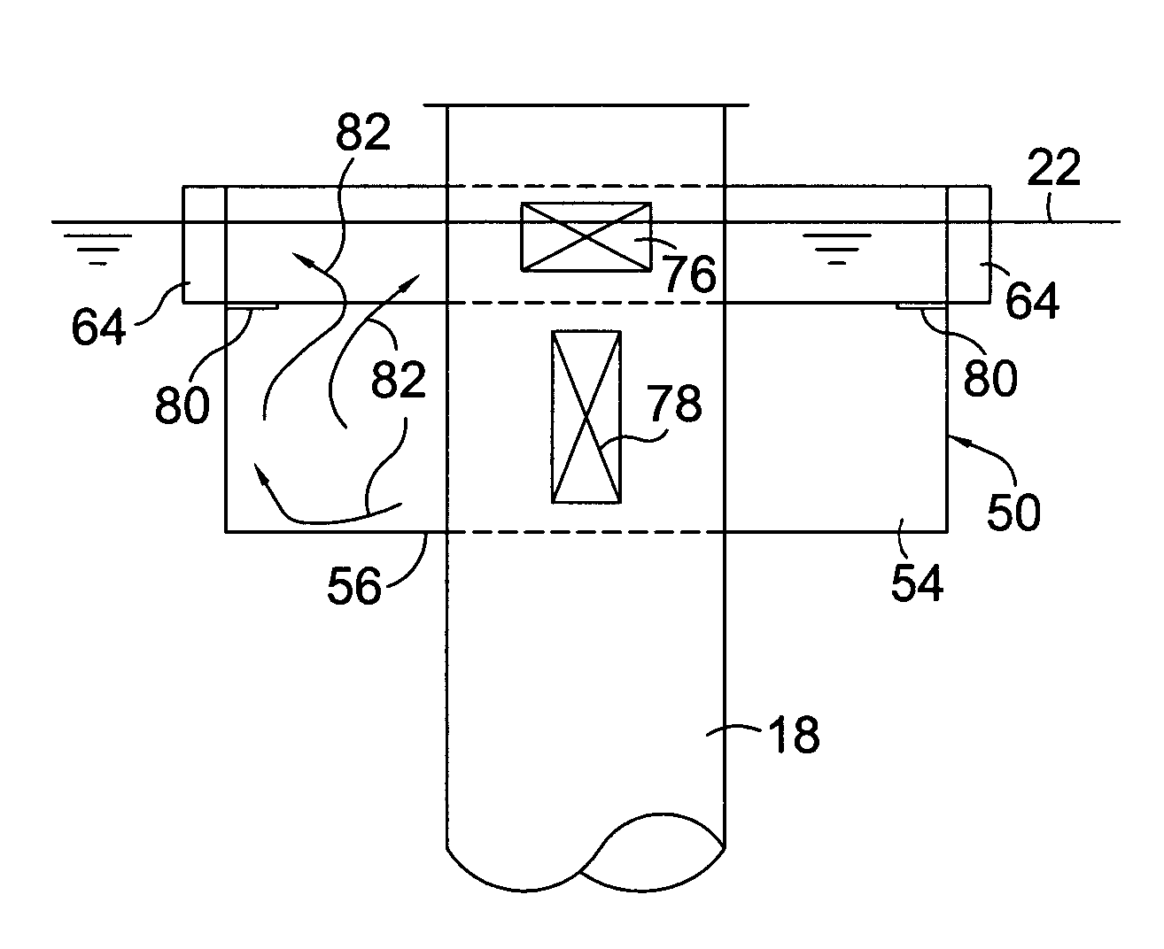
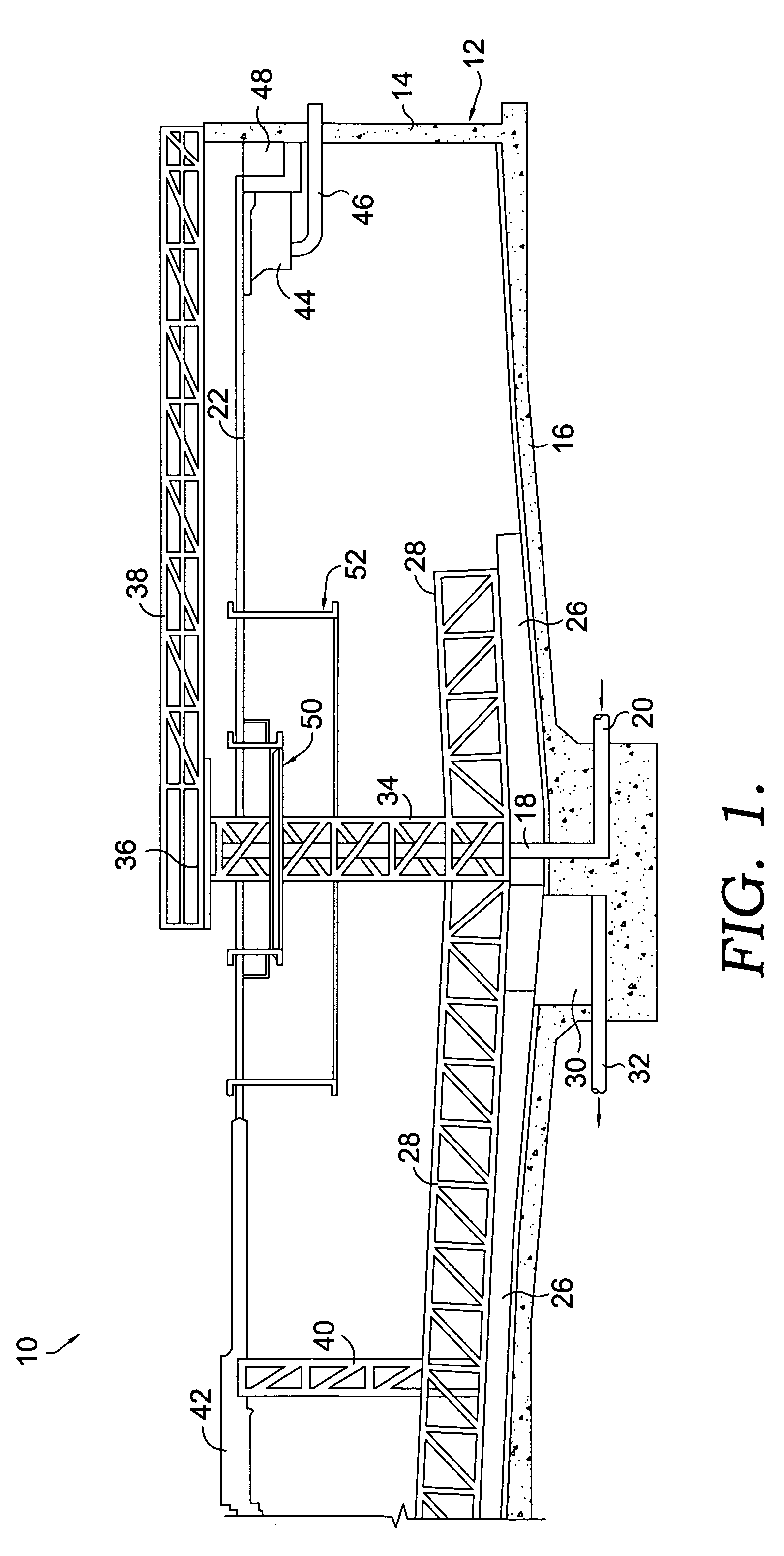
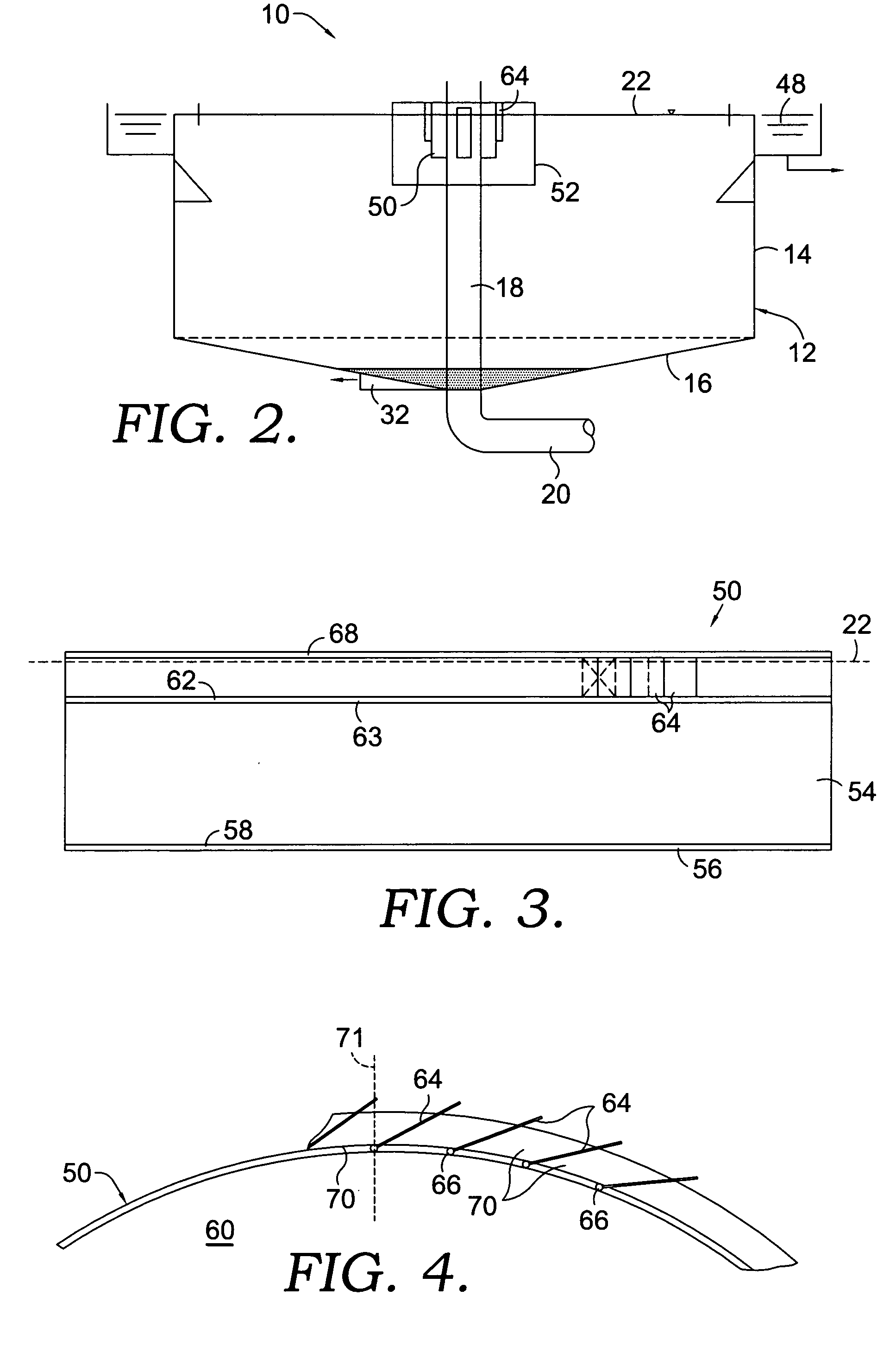
[0027] Referring now to the drawings in more detail and initially to FIG. 1, numeral 10 generally designates a clarifier which may be constructed conventionally for the most part. The clarifier 10 includes a clarifier basin 12 which receives influent liquid that is to be treated by removing solids. The clarifier basin 12 has a cylindrical sidewall 14 and a floor 16 which slopes downwardly toward the center. A vertical influent column 18 extends upwardly along the axial center of the basin 12. The influent that is to be treated is supplied to the influent column through an inlet pipe 20 which may extend under the floor 16. Below the liquid level 22 in the basin 12, the influent column 18 is provided with a plurality of ports 24 (see FIG. 5) which discharge the influent from the column 18.

[0028] The clarifier 10 is equipped with a plurality of rakes or blades 26 that are carried on rotating rake arms 28. As the arms 28 rotate, the blades 26 rake sludge which settles on the clarifier ...


PUM

PropertyMeasurementUnit
angleaaaaaaaaaa
angleaaaaaaaaaa
angleaaaaaaaaaa

Abstract

A clarifier is provided with an improved inlet structure which receives influent from influent column ports and discharges the influent uniformly around the entire circumference of the inlet structure. The influent column ports may be baffled. Angled guide vanes on the inlet structure reduce the flow energy and effect a tangential flow into a feedwell in the basin. The feedwell may be conical to further reduce the velocities and create an outward flow to counteract inward flows in the basin.

Description

CROSS-REFERENCE TO RELATED APPLICATIONS [0001] Not applicable. STATEMENT REGARDING FEDERALLY SPONSORED RESEARCH OR DEVELOPMENT [0002] Not applicable. FIELD OF THE INVENTION [0003] This invention relates generally to the clarification of liquids and more particularly to an improved inlet structure for controlling the flow characteristics of influent entering a clarification basin. BACKGROUND OF THE INVENTION [0004] Clarifiers of various sizes and types are commonly used in applications requiring the settling of solids from an influent liquid, such as in the treatment of water and wastewater. The influent is usually introduced into the clarifier from an influent column which extends in the center of the clarifier and has ports that discharge the influent from the column. Clarifiers are normally equipped with feedwells that take the form of rings extending around the influent column near the top of the clarifier basin. [0005] There are a number of flow characteristics of the influent t...

Claims


Application Information

Patent Timeline
Patent Type & Authority Applications(United States)
IPC IPC(8): B01D21/00B01D21/06B01D21/24
CPCB01D21/0042B01D21/02B01D21/06B01D21/2411B01D21/2433B01D21/2427
Inventor ALBERTSON, ORRIS E.
Owner ORRIS E ALBERTSON LEGACY LLC
Why Eureka
Try Eureka