Installation for supplying liquid feed to an animal and an autonomously displaceable vehicle for use in such an installation

a technology for installing and supplying liquid feed to animals, which is applied in the direction of animal feeding devices, aviculture, animal watering devices, etc., can solve the problems of large installation size, difficult installation, and, consequently, relatively expensive, and achieves flexible use and simple construction.

Inactive Publication Date: 2011-05-03
MAASLAND
View PDF35 Cites 4 Cited by
  • Summary
  • Abstract
  • Description
  • Claims
  • Application Information

AI Technical Summary

Benefits of technology

[0006]The present invention aims inter alia at providing an installation for supplying liquid feed to an animal, such as a calf, which installation may be of relatively simple construction, flexible in use and relatively cheap.
[0012]Autonomously displaceable vehicles for numerous applications are known per se, many different ways of automatically controlling the vehicle being used. Since there are several loading and unloading places in the installation according to the invention, it is advantageous, inter alia for keeping the temperature of the liquid feed as constant as possible, if the microprocessor or the like is provided with a computer with a memory, the memory being designed to contain data relating to expected and / or historical travelling times of a displaceable vehicle from a particular feed loading place to a relevant feed unloading place, and / or from a given feed unloading place to another feed unloading place and / or from a feed loading place to another feed loading place. This makes it possible, when supplying feed, not only to take the travelling times of the vehicle into account, but also to control the heating device at least partially with the aid of the data relating to the expected and / or historical travelling times. If, for example, the travelling time is proportionally long, the hot water can be proportionally hotter for keeping the liquid feed longer at a particular temperature.
[0014]In a preferred embodiment of the installation according to the invention, the drinking nozzle is movably mounted relative to the remaining part of the displaceable vehicle. This means that, on the one hand, it is possible, for example, to move the drinking nozzle forward in such a way that it is easily accessible for an animal and, on the other hand, it is possible to attune the position of the drinking nozzle to the dimensions of an animal. In the latter case, it is advantageous if the displaceable vehicle is provided with animal identification means for identifying an animal and for supplying an identification signal indicative of the identity of an animal, the identification signal, besides for other objectives, such as supplying particular sorts of feed, being used in particular for moving the drinking nozzle.
[0016]The milk obtained in such a milking machine being relatively warm, it would be advantageous to transport the milk obtained as quickly as possible to a relevant animal in order that as little energy as possible is needed to keep the milk at a particular temperature. In an embodiment of an installation according to the invention, this is achieved in that the milking machine comprises a detection device for detecting the arrival of an animal in the milking machine and for supplying a detection signal. Said detection signal can then be used for controlling the displacement of the displaceable vehicle, so that the vehicle is displaced to the relevant milking machine by means of the detection signal. In this manner it is possible for the vehicle to arrive at the milking machine as quickly as possible and to take the milk that has cooled as little as possible from the milking machine or a storage device located in its vicinity.
[0021]In order that the displaceable vehicle can pass in a simple manner through walls and the like of the installation, the installation is provided with gates closed by flexible means for enabling each displaceable vehicle to pass through.

Problems solved by technology

This means that the known installation is relatively large in size and difficult to install and, consequently, relatively expensive.
However, this known vehicle is not suitable for supplying liquid feed, such as milk, directly to an animal, such as a calf.

Method used


Image

  • Installation for supplying liquid feed to an animal and an autonomously displaceable vehicle for use in such an installation
  • Installation for supplying liquid feed to an animal and an autonomously displaceable vehicle for use in such an installation
  • Installation for supplying liquid feed to an animal and an autonomously displaceable vehicle for use in such an installation

Examples


Embodiment Construction

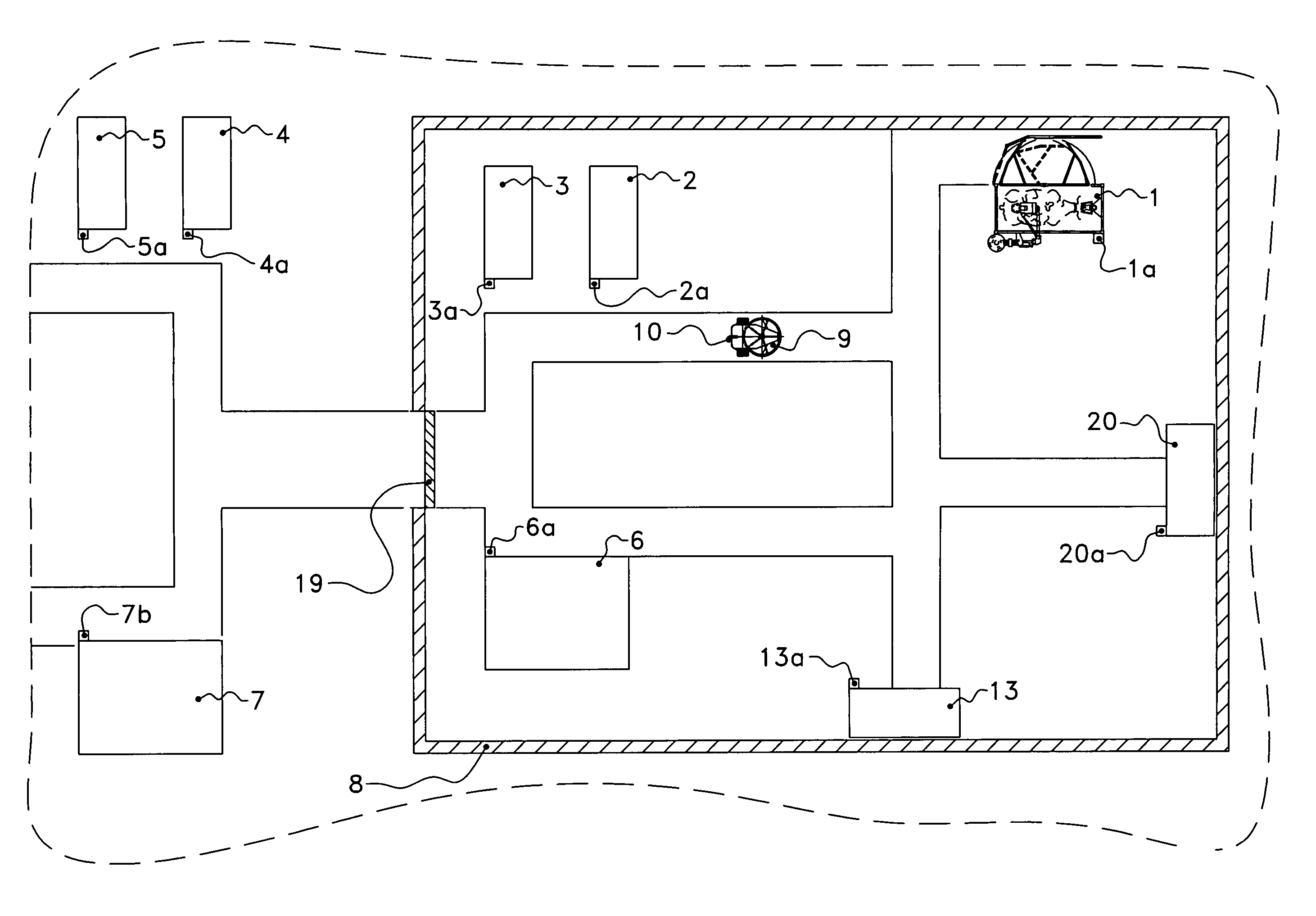
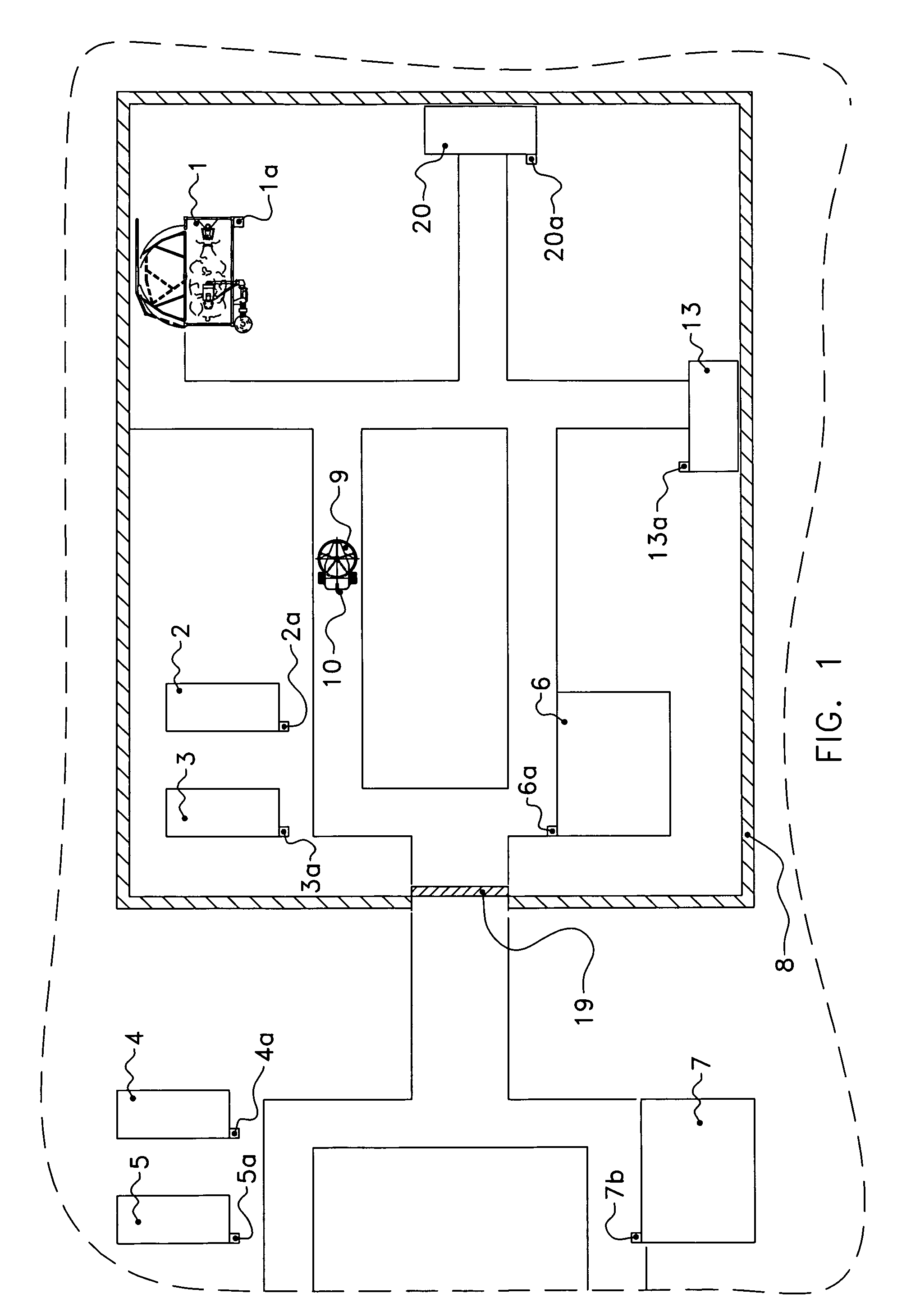
[0026]An installation for supplying liquid feed to an animal, such as a calf, is shown in a diagrammatic plan view in FIG. 1. The installation comprises one or more feed loading places, in the embodiment shown in FIG. 1 a milking machine 1, in the example a milking machine with a (non-shown) device for automatically connecting teat cups to the teats of a dairy animal. The installation also comprises one or more feed unloading places 2-7, the situation in the embodiment shown in FIG. 1 being such that the feed unloading places 2, 3 and 6 are located in a stable 8 and that the feed unloading places 4, 5 and 7 are located outside the stable 8. Moreover, the feed unloading places 2, 3, 4, 5 are feed unloading places for containing only one animal, so-called igloo housings, and the feed unloading places 6, 7 are suitable for containing several animals.

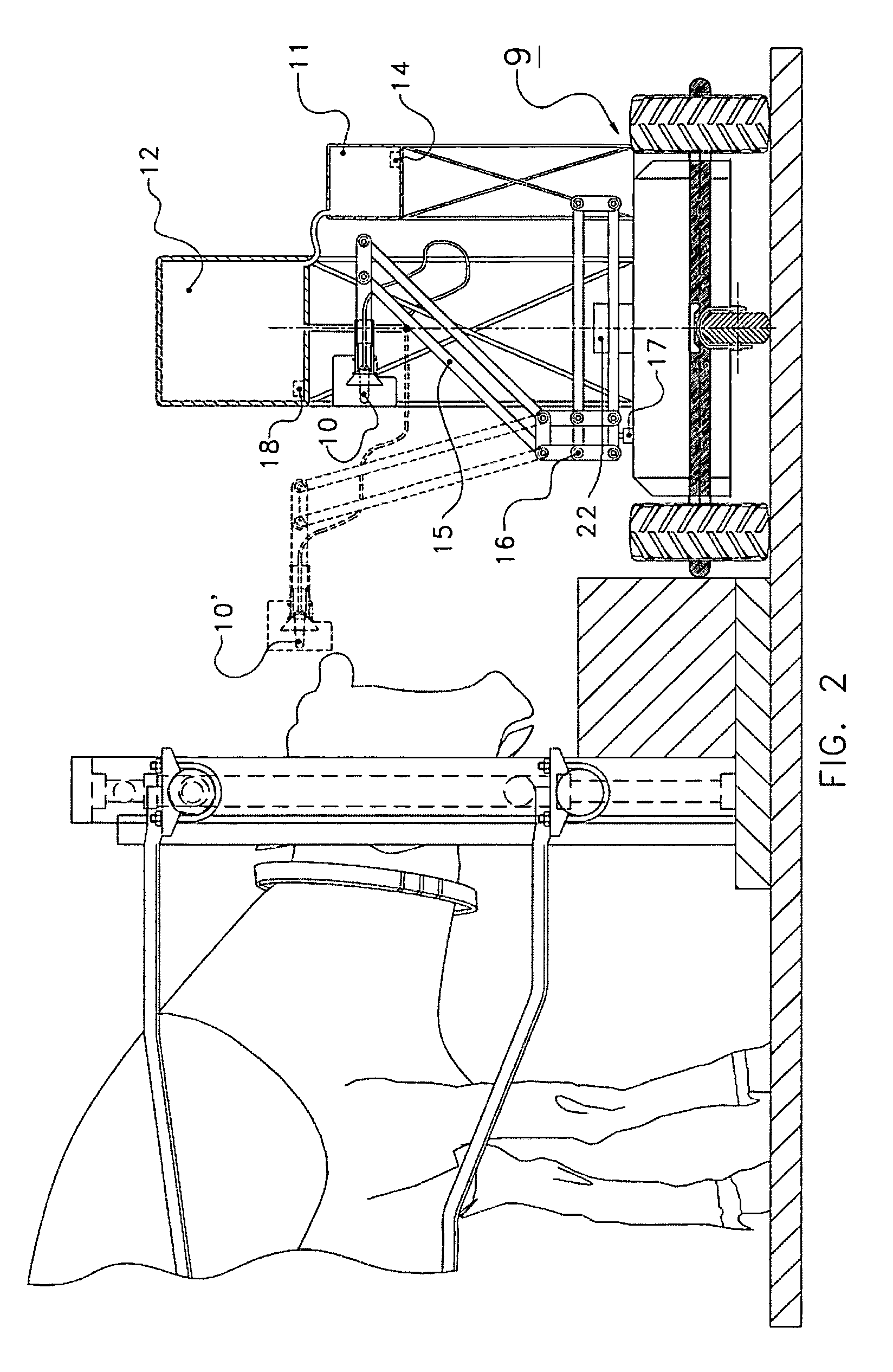
[0027]The installation further comprises one or more vehicles that are autonomously displaceable, controlled by a microprocessor 22 or the...


PUM


Abstract

An installation for supplying liquid feed to an animal, such as a calf. The installation comprises one or more feed loading places (1) and one or more feed unloading places (2-5), and one or more vehicles (9) that are autonomously displaceable, controlled by a microprocessor or the like, between one or more feed loading places and one or more feed unloading places, each vehicle comprising a drinking nozzle (10), such as a flexible teat.

Description

CROSS REFERENCE TO RELATED APPLICATIONS[0001]This application is a continuation of International Application No. PCT / NL2006 / 000568 filed on Nov. 14, 2006, which was published under PCT Article 21(2) in English, the contents of which are hereby incorporated by reference in their entirety.BACKGROUND OF THE INVENTION[0002]1. Field of the Invention[0003]The present invention relates to an installation for supplying liquid feed to an animal, such as a calf.[0004]2. Description of the Related Art[0005]An installation is known from EP-B1-1037524 the contents of which are hereby incorporated by reference in their entirety. This known installation comprises a milking machine for producing milk. This milk is either directly supplied to an animal or first stored in a storage device and subsequently automatically supplied to an animal. The known installation further comprises a line system for transporting the milk obtained from the milking machine to an animal, such as a calf, or to the storag...

Claims


Application Information

Patent Timeline
Patent Type & Authority Patents(United States)
IPC IPC(8): A01J7/00A01K7/00A01K9/00
CPCA01K9/00A01K5/0266A01K5/0216
Inventor VAN DEN BERG, KAREL
Owner MAASLAND
Why Eureka
Try Eureka