
Patient-ventilator synchronization using dual phase sensors

a technology of patient and ventilator, applied in the direction of respirator, valve operating device/release device, instruments, etc., can solve the problems of not ensuring any particular ventilation, no guaranteed minimum ventilation, and little effort to keep the support precisely in phase with the patient's own respiratory effor

Inactive Publication Date: 2011-05-03
RESMED LTD
View PDF33 Cites 95 Cited by
  • Summary
  • Abstract
  • Description
  • Claims
  • Application Information

AI Technical Summary

Benefits of technology

The system delivers ventilatory support precisely in phase with the patient's efforts, ensuring a targeted minimum ventilation even during irregular breathing, while being immune to leaks and maintaining synchronization with respiratory efforts.

Problems solved by technology

Thus, these devices supply a fixed degree of support A. However, they do not guarantee any particular ventilation when, for example, the patient's efforts are inadequate.
However, again, in the case of a patient's efforts being inadequate, for example, due to reduced chemoreflex control of breathing during sleep, there is no guaranteed minimum ventilation.
Unfortunately, while this method achieves a guaranteed minimum ventilation, there is little attempt to keep the support precisely in phase with the patient's own respiratory efforts.
However, in this AutoVPAP system, room for improvement exists in the phase determination due to the problem of leak.
Mask and / or mouth leak is ubiquitous during noninvasive ventilatory support using a mask, and is particularly problematical during sleep.
Leak causes mis-measurement of the respiratory airflow, and therefore can severely interfere with patient-machine synchronization.

Method used


Image

  • Patient-ventilator synchronization using dual phase sensors
  • Patient-ventilator synchronization using dual phase sensors
  • Patient-ventilator synchronization using dual phase sensors

Examples


Embodiment Construction

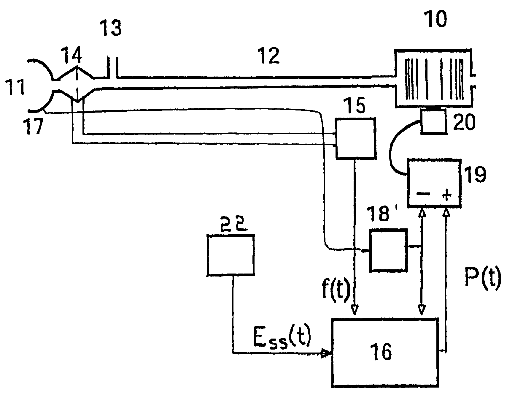
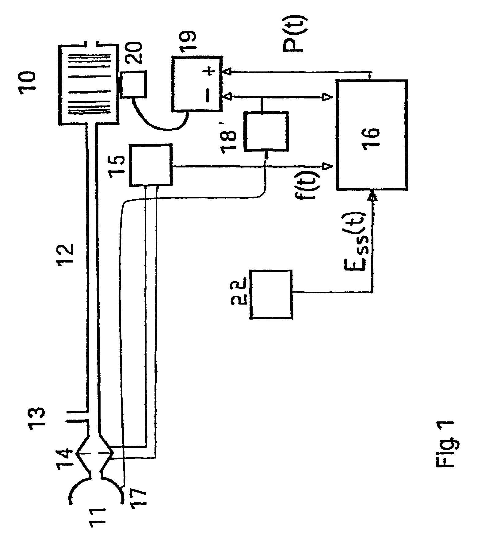
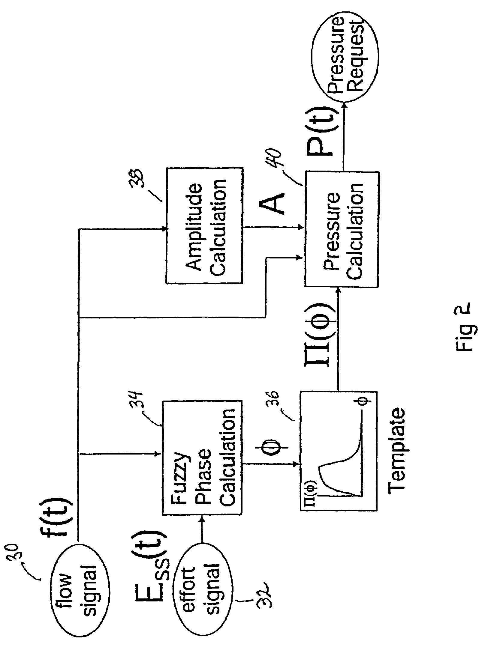
[0050]A servo-controlled ventilator useful for accomplishing the present invention is shown in FIG. 1. A blower 10 supplies air under pressure via delivery tube 12 to a mask 11. Exhaust gas is vented via exhaust 13. Mask flow is measured using pneumotachograph 14 and differential pressure transducer 15 to derive flow signal f(t). Mask pressure is measured at pressure tap 17 using pressure transducer 18. Respiratory effort is measured by an effort sensor 22 to yield an effort signal Ess(t). Flow, effort and pressure signals are sent to microcontroller 16 which implements the processing shown in FIG. 2 to derive a pressure request signal P(t). The actual measured pressure and pressure request signal P(t) are fed to motor servo 19 which controls blower motor 20 to produce the desired instantaneous mask pressure. An example of this type of ventilator, without an effort sensor 22, is the subject of International Publication No. WO 98 / 12965, which is also disclosed in related U.S. applica...


PUM


Abstract

An improved ventilator which delivers ventilatory support that is synchronized with the phase of the patients respiratory efforts and guarantees a targeted minimum ventilation. Improved synchronization is achieved through an instantaneous respiratory phase determination process based upon measured respiratory airflow as well as measured respiratory effort using an effort sensor accessory, preferably a suprasternal notch sensor. The ventilator processes a respiratory airflow signal, a respiratory effort signal and their respective rates of change to determine a phase using standard fuzzy logic methods. A calculated pressure amplitude is adjusted based upon the calculated phase and a smooth pressure waveform template to deliver synchronized ventilation.

Description

RELATED APPLICATION[0001]This application is a continuation of U.S. application Ser. No. 10 / 986,471 filed Nov. 11, 2004, now U.S. Pat. No. 7,055,522, which is a continuation of U.S. application Ser. No. 09 / 661,998 filed Sep. 14, 2000, now U.S. Pat. No. 6,910,480 which claims the priority date of U.S. Provisional Application Ser. No. 60 / 154,196 filed Sep. 15, 1999.FIELD OF THE INVENTION[0002]This invention relates to a method and device for providing ventilatory assistance to a patient. More specifically, the invention involves an improved method and device that provides ventilation in phase with a patient's respiratory efforts through the use of a respiratory effort sensor.BACKGROUND OF THE INVENTION[0003]Devices for providing mechanical ventilation to assist patient respiration are well known. Such ventilator devices have been used to help patients with such ailments as severe lung disease, chest wall disease, neuromuscular disease and other diseases of respiratory control. General...

Claims


Application Information

Patent Timeline
Patent Type & Authority Patents(United States)
IPC IPC(8): A61M15/00A61M16/00A62B7/00
CPCA61M16/00A61M16/0066A61M2230/60A61M2016/0036A61M2016/0021A61M16/0069A61M16/024
Inventor BERTHON-JONES, MICHAEL
Owner RESMED LTD
Learn More