
Derivation of flow contour from pressure waveform

a flow contour and pressure waveform technology, applied in the field of hemodynamic monitoring devices and methods, can solve the problems of inability to realize clinically direct monitoring of flow chronically in ambulatory patients, the use of methods that require frequent calibration, and the inability to account for variations in vascular impedan

Active Publication Date: 2011-05-03
MEDTRONIC INC
View PDF18 Cites 8 Cited by
  • Summary
  • Abstract
  • Description
  • Claims
  • Application Information

AI Technical Summary

Benefits of technology

Enables continuous monitoring of blood flow and hemodynamic parameters, such as cardiac output and vascular impedance, with reduced need for calibration, providing accurate tracking of changes in response to clinical interventions.

Problems solved by technology

However, direct monitoring of flow chronically in an ambulatory patient has not been realized clinically.
Pressure measurements alone do not account for variations in vascular impedance, which changes in response to varying physiological conditions and is time-varying over the cardiac cycle.
Pressure pulse contour cardiac output methods have been developed for estimating flow from arterial pressure signals, however, such methods generally require frequent calibration, particularly after a suspected change in hemodynamics.

Method used


Image

  • Derivation of flow contour from pressure waveform
  • Derivation of flow contour from pressure waveform
  • Derivation of flow contour from pressure waveform

Examples


Embodiment Construction

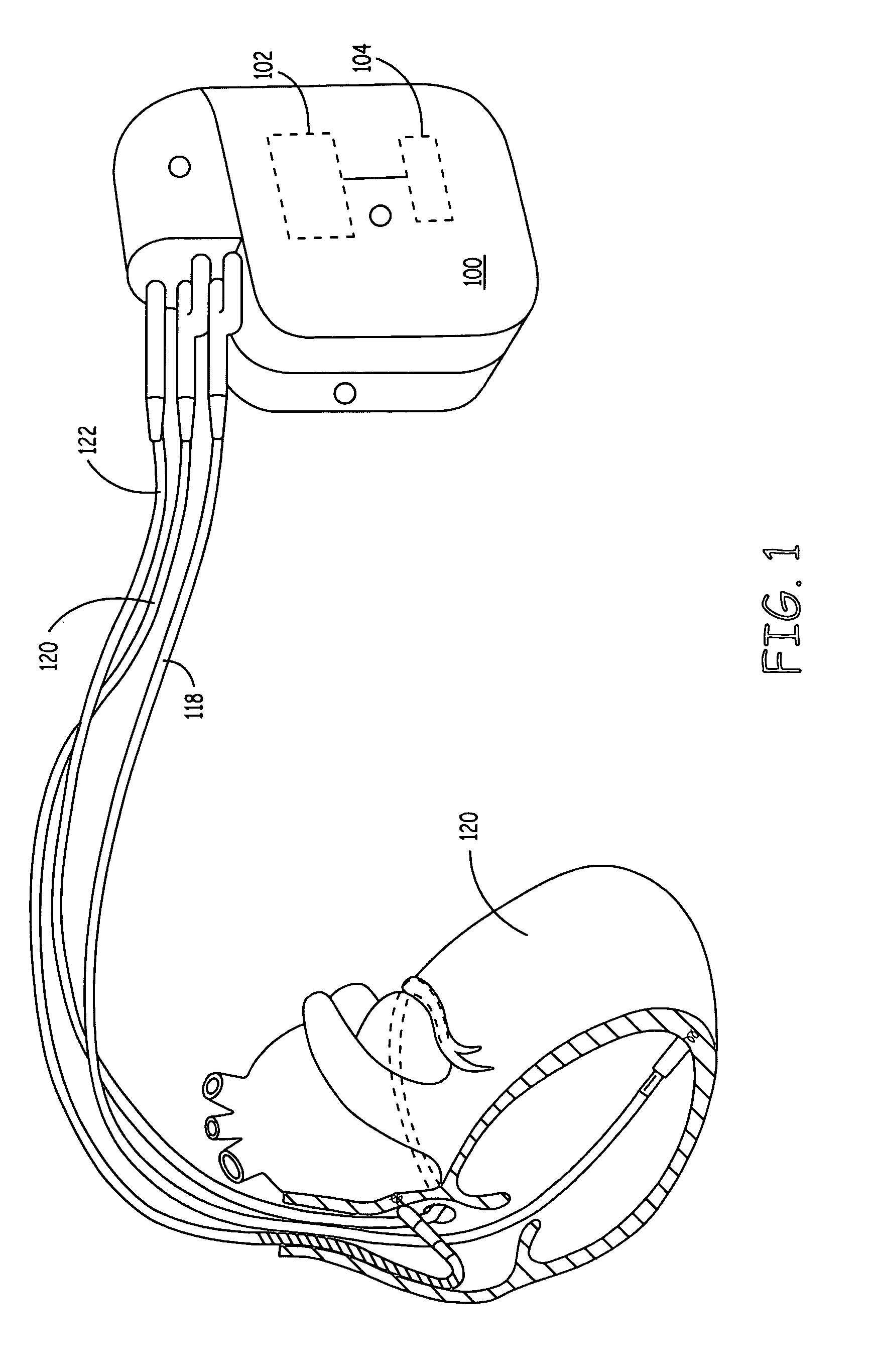
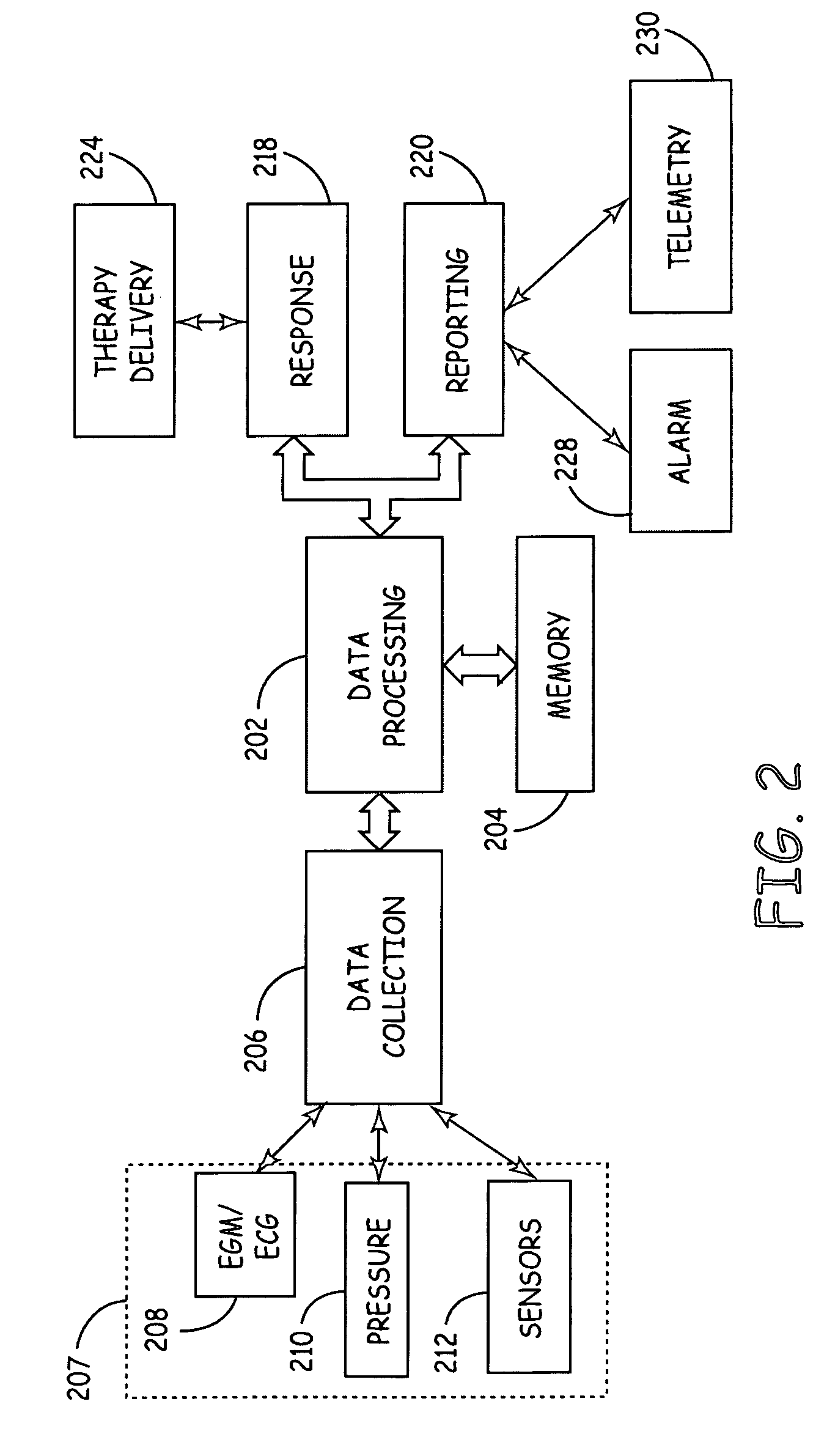
[0021]FIG. 1 is an illustration of an exemplary implantable medical device (IMD) 100 connected to monitor a patient's heart 120. IMD 100 may be configured to integrate both monitoring and therapy features, as will be described below. IMD 100 collects and processes data about heart 120 from one or more sensors including a pressure sensor and an electrode pair for sensing cardiac electrogram (EGM) signals. IMD 100 may further provide therapy or other response to the patient as appropriate, and as described more fully below. As shown in FIG. 1, IMD 100 may be generally flat and thin to permit subcutaneous implantation within a human body, e.g., within upper thoracic regions or the lower abdominal region. IMD 100 is provided with a hermetically-sealed housing that encloses a processor 102, a digital memory 104, and other components as appropriate to produce the desired functionalities of the device. In various embodiments, IMD 100 is implemented as any implanted medical device capable o...


PUM


Abstract

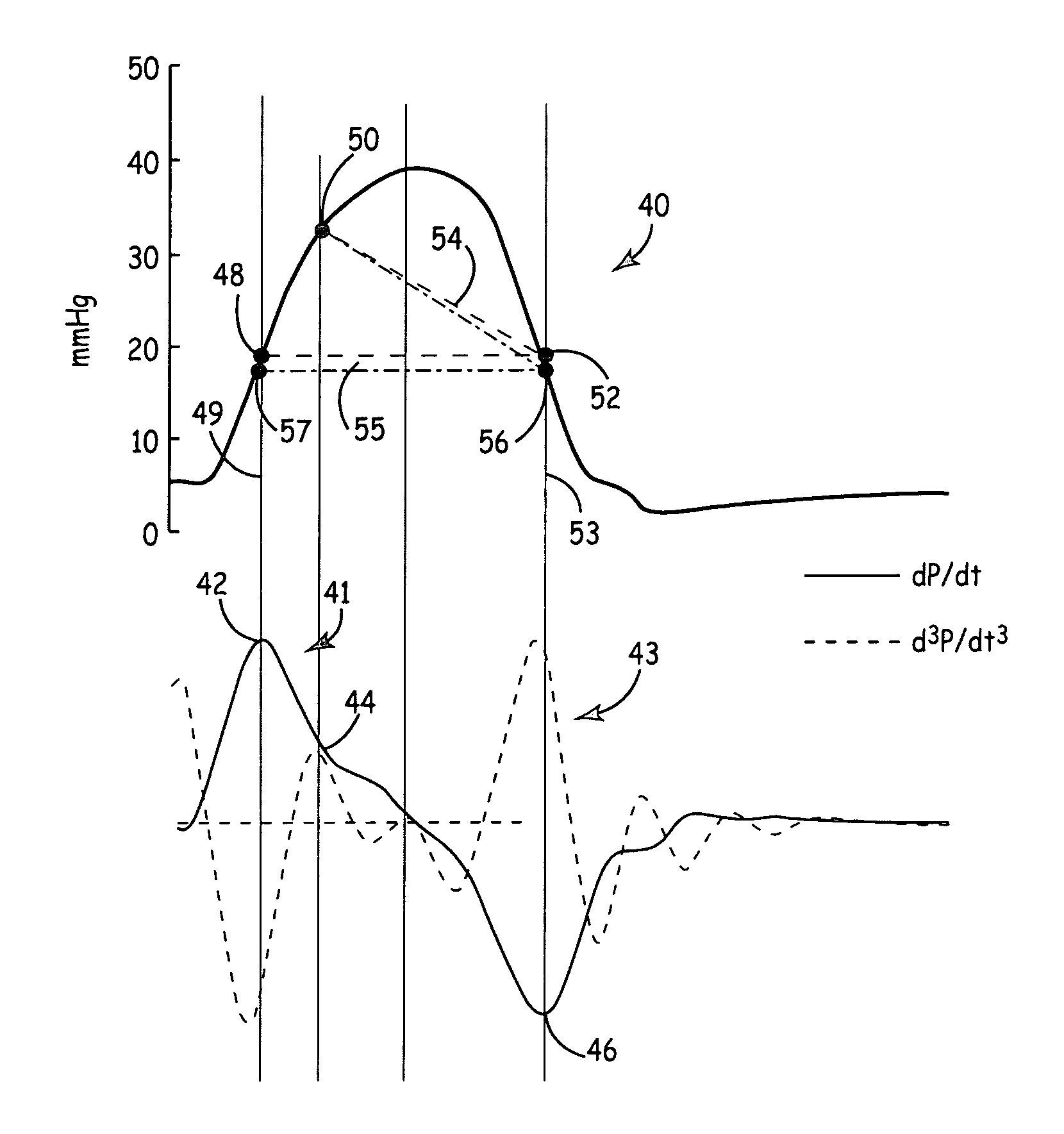
The present invention provides a system and method for estimating a blood flow waveform contour from a pressure signal. An arterial or ventricular pressure signal is acquired from a pressure sensor. Landmark points are identified on the pressure waveform that correspond to features of a flow waveform. In one embodiment, the landmark pressure waveform points correspond to the onset of flow, the peak flow, and the end of the systolic ejection phase. The landmark pressure waveform points define a contour that approximates the flow contour. Beat-by-beat flow contour estimation can be performed to allow computation of flow-related hemodynamic parameters such as stroke volume or cardiac output for use in patient monitoring and / or therapy management.

Description

FIELD OF THE INVENTION[0001]The present invention relates generally to hemodynamic monitoring devices and methods and particularly to a method and apparatus for deriving a blood flow contour from a pressure waveform.BACKGROUND OF THE INVENTION[0002]Implantable hemodynamic monitors are available for monitoring right ventricular pressure chronically in an ambulatory patient. Patients with congestive heart failure (CHF) have elevated cardiac filling pressures and reduced cardiac output. A major treatment objective is to lower filling pressures while maintaining adequate cardiac output. Therefore, from a hemodynamic monitoring perspective, it is advantageous to monitor both filling pressures and measures of cardiac output.[0003]Chronic pressure monitoring in ambulatory patients using chronically implantable pressure sensors has been realized. However, direct monitoring of flow chronically in an ambulatory patient has not been realized clinically. Pressure measurements alone do not accou...

Claims


Application Information

Patent Timeline
Patent Type & Authority Patents(United States)
IPC IPC(8): A61B5/02
CPCA61B5/0215A61B5/7239A61B5/029A61B5/02108
Inventor KARAMANOGLU, MUSTAFABENNETT, TOMMY D.
Owner MEDTRONIC INC
Learn More