Dynamic window jamb channel block

a window jamb and channel block technology, applied in the field of window frames, can solve problems such as large window openings, and achieve the effect of large window openings

Active Publication Date: 2011-05-10
CALDWELL MFG NORTH AMERICA
View PDF14 Cites 12 Cited by
  • Summary
  • Abstract
  • Description
  • Claims
  • Application Information

AI Technical Summary

Benefits of technology

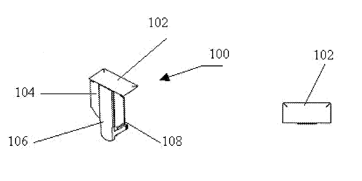
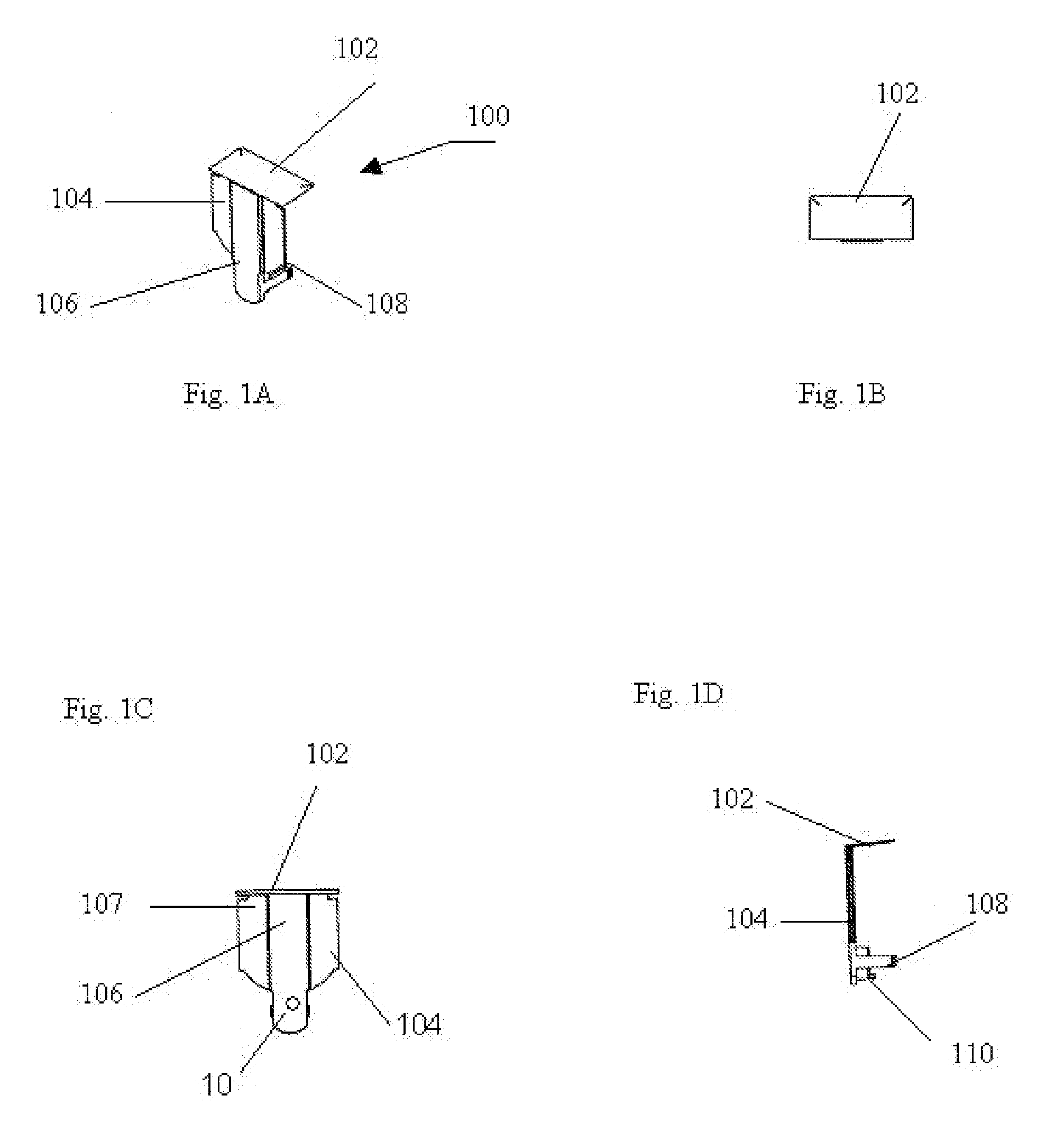
[0007]The device of the present invention is called a dynamic chimney block. It is referred to as being dynamic because it is allowed to move vertically up and down the jamb channel and not interfere with the movement of the carrier. Further, this flexibility in movement allows for greater movement of the sash, which results in a larger window opening.
[0008]The main purpose of the dynamic chimney block is to impede or substantially reduce the vertical movement of air through the jamb channel. The reduction in air movement improves the insulating properties of the window and minimizes the amount of dust and fine dirt that might otherwise enter the jamb channel which would result in a progressively increasing force required to move the sash through the jamb channel.

Problems solved by technology

Further, this flexibility in movement allows for greater movement of the sash, which results in a larger window opening.

Method used


Image

  • Dynamic window jamb channel block
  • Dynamic window jamb channel block
  • Dynamic window jamb channel block

Examples


Embodiment Construction

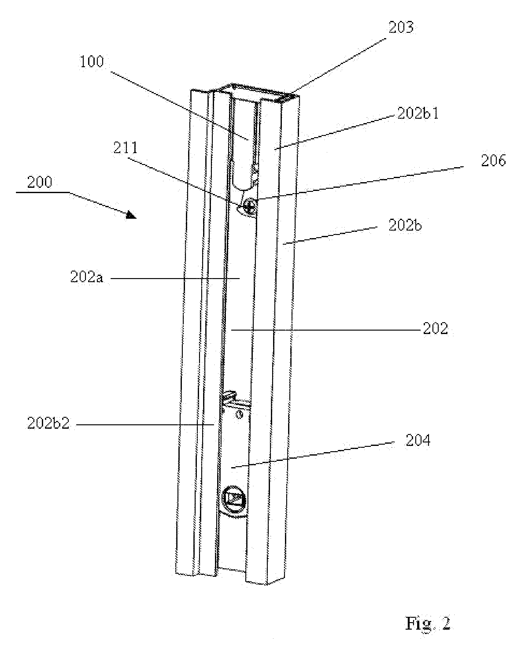
[0015]Referring first to FIG. 2, what is shown is a cut away of the jamb section 200 of a window frame (not fully shown). The jamb 200 contains a channel, known as a jamb channel 202. The jamb channel 202 provides the route through which a carrier travels with the vertical movement of the sash (not shown). The presently indicated carrier is a curl spring carrier 204, which will be shown in more detail in subsequent figures.

[0016]With respect to curl spring carriers, such as 204, an elongated spring is coiled within the body of the curl spring carrier 204. The end of the spring which extends outward from the body of the carrier is secured at a specific location in the jamb channel 202 by a mounting bracket 206 (best shown in FIG. 4). With one end of the spring secured to the wall of the jamb channel 202, the curl spring carrier 204 rides up and down the jamb channel 202 with the movement of the sash.

[0017]The jamb channel 202 must be large enough to accommodate the dimensions of the ...


PUM


Abstract

The device of the present invention is identified as a chimney block for use in the jamb channels of window frames. The chimney block impedes or substantially reduces the vertical movement of air through the jamb channel. The reduction in air movement improves the insulating properties of the window and minimizes the amount of dust and fine dirt that might otherwise enter the jamb channel resulting in a progressively increasing force required to move the sash through the jamb channel. It consists of a vertical structural element which is secured to a planar sealing element that conforms to the cross section of the jamb channel. Legs or struts are attached in proximity to the other end of the vertical structural element to insure that the chimney block essentially remains in the same position to provide an air block.

Description

FIELD OF THE INVENTION[0001]The invention pertains to the field of window frames. More particularly, the invention pertains to a moveable device that travels up and down the jamb channel of the window frame with the movement of the sash to impede the transfer of air and debris into and through the jamb channel.BACKGROUND OF THE INVENTION[0002]Window frames may consist of either a single sash or two sashes, and are referred to, respectively, as single or double hung windows. A window assembly generally includes a window frame, at least one sash, a pair of opposing window jambs, each jamb having a channel for allowing the vertical travel of each sash, and usually a balance to assist with the raising and lowering of the sash to which it is attached by providing a counterbalance force to the weight of the sash.[0003]The jambs are vertically positioned on either side of the sash within the window frame assembly. Because they must provide a space to permit the sash shoe or carrier to free...

Claims


Application Information

Patent Timeline
Patent Type & Authority Patents(United States)
IPC IPC(8): E05D13/00
CPCE05D15/22E06B7/10E05D13/1276E05Y2900/148Y10T16/6298E05Y2201/684
Inventor TULLER, JEFFREY
Owner CALDWELL MFG NORTH AMERICA
Why Eureka
Try Eureka