Autostereoscopic projection system

a projection system and autostereoscopic technology, applied in the field of autostereoscopic projection system and autostereoscopic projection system, can solve the problems of pseudo-stereo images in prior systems, and achieve the effects of low resolution, small image, and low and/or varying brightness

Active Publication Date: 2011-05-10
DISNEY ENTERPRISES INC
View PDF18 Cites 19 Cited by
  • Summary
  • Abstract
  • Description
  • Claims
  • Application Information

AI Technical Summary

Benefits of technology

[0010]Previous autostereoscopic systems have used lenticular screens or vertical barrier strips in an attempt to get each of the viewer's eyes to see only a right or a left eye image. These systems were not widely adopted because they typically had low resolution, could only have relatively small images, and often had low and / or varying brightness such as when the viewer moved their head. Some prior systems also suffered from zones or areas of pseudo-stereo images in which the right and left eye images were reversed. Other prior devices only worked if eye location was traced accurately such that the projection system could operate to track that location to display the proper image at the corresponding eye location. In contrast, embodiments of the invention allow a user to move within a projection space or area that corresponds with virtual projector positions without concern about right or left eye location. Instead, the viewer's eyes are naturally aligned with two spaced-apart projected images reflected from the retroreflective screen and the beam splitter (in one embodiment, at least) so as to perceive a 3D image.
[0011]The projection systems and embodiments allow a show or optical illusion designer to place an image within a dimensional set or scene, with the image being bright and solid enough in quality to appear to be there in the scene (e.g., to appear less ghostly than prior devices unless that is the desired effect which can then be achieved by selecting a less reflective splitter and / or less powerful projector or by using brighter lighting on the background objects). The displayed images in the display viewing zone / area (such as a ride vehicle window, a port hole as found in a submarine / ship, a viewing window, and the like) has multiple POVs and not just a single left and right eye image, and, hence, the image does not distort by “following” the viewer as he moves, which allows the designer to interface it precisely with real objects in the scene / set in close proximity (without bleeding into these images and other problems).

Problems solved by technology

These systems were not widely adopted because they typically had low resolution, could only have relatively small images, and often had low and / or varying brightness such as when the viewer moved their head.
Some prior systems also suffered from zones or areas of pseudo-stereo images in which the right and left eye images were reversed.

Method used


Image

  • Autostereoscopic projection system
  • Autostereoscopic projection system
  • Autostereoscopic projection system

Examples


Embodiment Construction

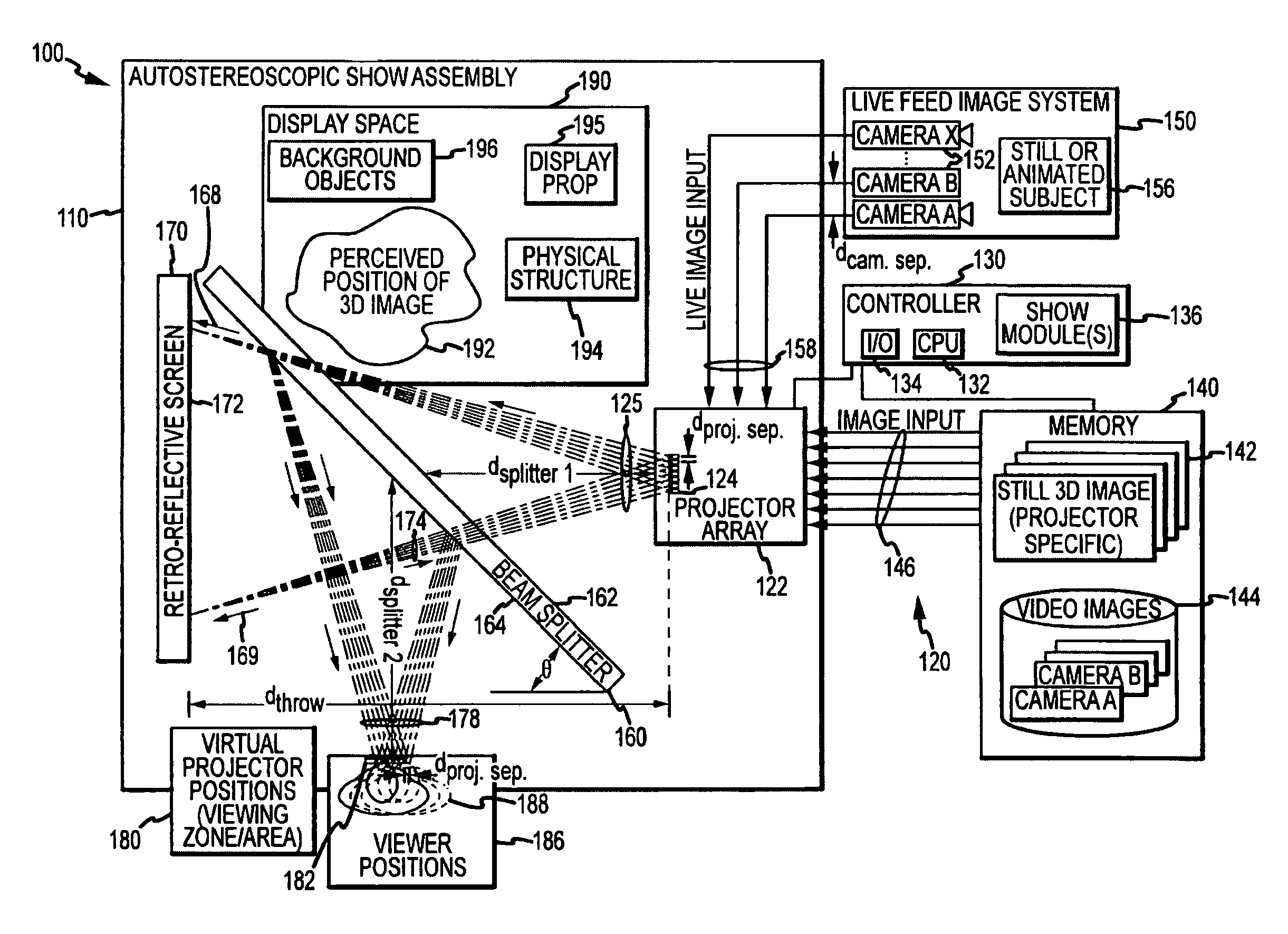
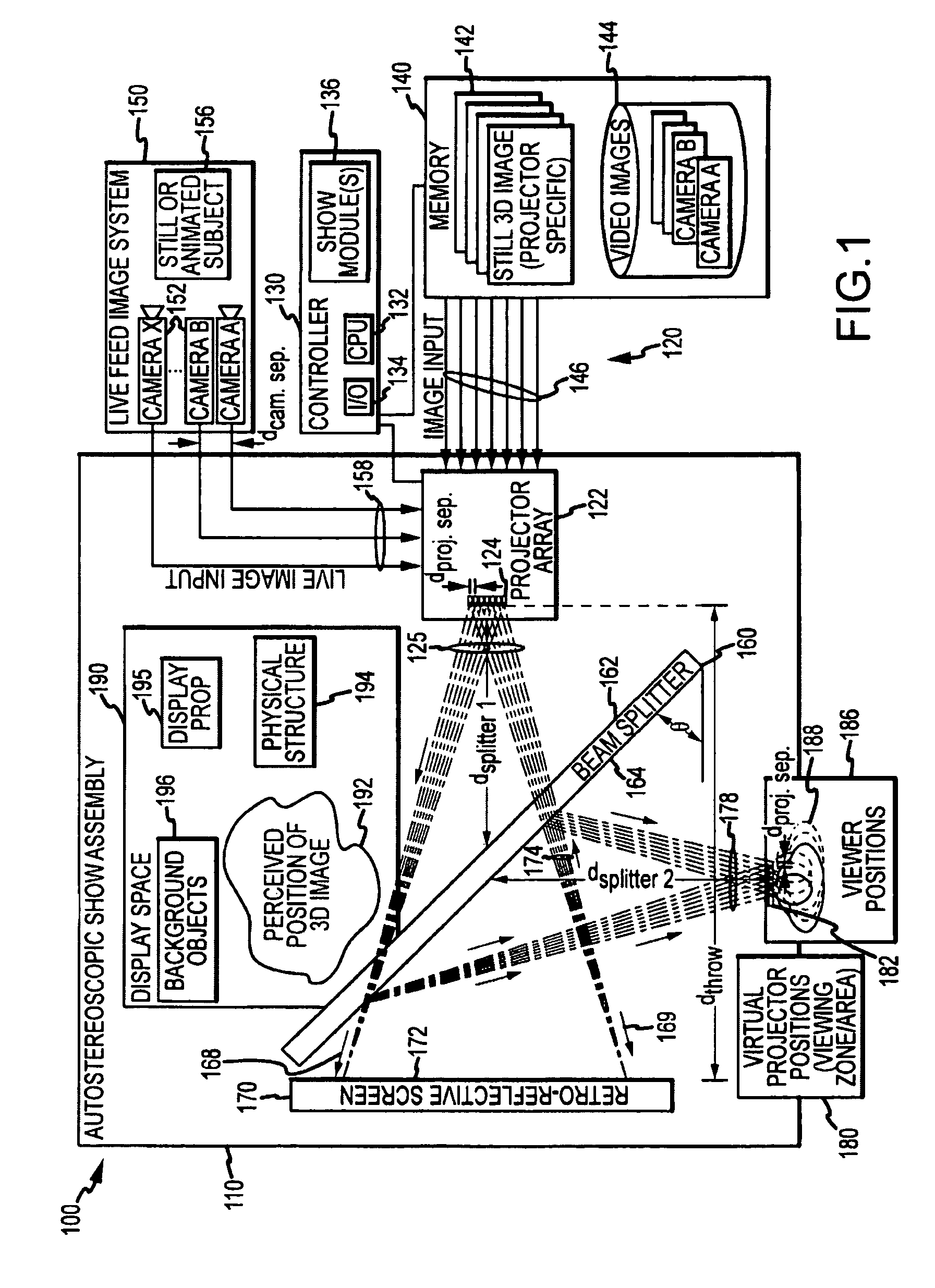
[0025]Briefly, embodiments of the present invention are directed to 3D or autostereoscopic projection systems, and associated methods, for projecting or displaying an image having depth to one or more viewers. The projection method involves providing a projector array or assembly with one or more rows of projectors that are each spaced apart a projector distance (e.g., projectors within a row but in differing columns and projectors in differing rows are spaced apart from neighboring or adjacent projectors by about the human interoccular distance or less). An image stream or image data is input or fed to each of these projectors, with the images being provided to each projector from a camera or a camera position / POV that typically corresponds in location to that of the projector in the array (e.g., similar spacing of cameras or software tools / cameras used in animation). The projectors transmit along a number of spaced apart, parallel paths onto a retroreflective screen (or surface of...


PUM


Abstract

An apparatus projecting 3D autostereoscopic images viewers. The apparatus includes a projector array with projectors each receiving an input image such as digital video and projecting an image based on the input image. A beam splitter with first and second surfaces is positioned such that the projected images strike the first surface and a portion (e.g., 50 to 95 percent) is transmitted through the beam splitter toward a screen with a retroreflective surface. The retroreflective surface reflects the splitter-transmitted portion back along the same path but with increased brightness. The light reflected from the retroreflective surface strikes the second surface of the beam splitter and is reflected toward a display viewing zone provided at about the focal points of the reflected projectors. A 3D image is perceivable to a viewer who positions his eyes at or near any of two or more viewing locations proximate to the projection surface.

Description

BACKGROUND OF THE INVENTION[0001]1. Field of the Invention[0002]The present invention relates, in general, to projecting or displaying video / animated or still three dimensional (3D) images, and, more particularly, to autostereoscopy and autostereoscopic projection systems such as those adapted to display ghost or latent 3D images without requiring accurate tracking of a viewer's right and left eye or glasses, headgear, or other equipment that has to be worn or used by a viewer.[0003]2. Relevant Background[0004]There are numerous entertainment and other settings where it is desirable to create a unique visual display. For example, theme or amusement parks may include rides or walk-through attractions where guests (or “viewers”) are entertained by a unique visual effect or illusion. Pepper's ghost is an illusionary technique used by magicians, by ride or attraction designers, and others to produce a 3D illusion of a latent or ghost-like image. Using a simple piece of plate glass and s...

Claims


Application Information

Patent Timeline
Patent Type & Authority Patents(United States)
IPC IPC(8): G03B21/00H04N13/363
CPCG02B27/2292H04N13/0459H04N13/0402G03B21/00H04N13/302H04N13/363G02B30/56
Inventor BRENTNALL, III, THOMAS E.TURNER, RICHARD B.
Owner DISNEY ENTERPRISES INC
Why Eureka
Try Eureka