Thermally assisted magnetic head, head gimbal assembly, and hard disk drive

a magnetic head and head gimbal technology, applied in the field of magnetic head and head gimbal assembly, can solve the problems of large variation in characteristics among products, large reduction in light propagation efficiency, etc., and achieve the effect of reducing the characteristic variation among products and reducing the character variation

Active Publication Date: 2011-05-10
TDK CORPARATION
View PDF42 Cites 12 Cited by
  • Summary
  • Abstract
  • Description
  • Claims
  • Application Information

AI Technical Summary

Benefits of technology

[0026]The present invention has been accomplished in view of this problem, and an object of the present invention is to provide a thermally assisted magnetic head capable of reducing the characteristic variation among products, an HGA with this thermally assisted magnetic head, and a hard disk drive with this HGA.
[0028]Since the light emitting element is fixed to the light source support substrate and the first surface of the slider substrate is fixed to the second surface of the light source support substrate, the slider substrate and the light emitting element are kept in a fixed positional relation. Since the light emitting element faces the light entrance face of the core, the light does not propagate over a long distance, different from the conventional technology, and the light emitted from the light emitting element can be guided to the medium-facing surface, while permitting some mounting error and coupling loss of light.
[0030]Since the spot size w of the light intensity distribution along the X-axis on the XY plane is larger than the thickness of the core, the intensity of the light incident into the core will not vary so much even if the centroid position of the incident light is slightly shifted in the X-axis direction. Therefore, the variation is small in the intensity of the emerging light to irradiate the magnetic recording medium whereby the characteristic variation can be reduced among products.
[0032]Preferably, the thermally assisted magnetic head of the present invention further comprises a plasmon probe disposed on the light exit face of the core. When the plasmon probe is disposed on the light exit face of the core, it generates near-field light upon irradiation with the light from the light emitting element. When the plasmon probe is irradiated with light, electrons in metal making up the plasmon probe come to oscillate in a plasma (plasma oscillation) to cause concentration of the electric field at the distal end of the probe. Since a spread of this near-field light is approximately equal to the radius of the distal end of the plasmon probe, we can enjoy a pseudo effect of narrowing down the emerging light to below the diffraction limit if the radius of the distal end is set to below the track width.
[0038]In the HGA and the hard disk dive with the foregoing thermally assisted magnetic head, the characteristic variation can be reduced among products.
[0039]The thermally assisted magnetic head, and the HGA and the hard disk drive with this thermally assisted magnetic head according to the present invention are able to reduce the characteristic variation among products.

Problems solved by technology

However, when the light source is located at the place far from the slider, the optical fiber, lens, mirror, etc. have to be used over a long distance for guiding light, which poses a problem of large reduction in efficiency of propagation of light.
However, if there occurs a lateral shift between the optical axis of the light from the light emitting element and the optical axis on a light entrance face of the waveguide, the output of light emerging from the waveguide will vary largely, to cause a problem of large variation in characteristics among products.

Method used


Image

  • Thermally assisted magnetic head, head gimbal assembly, and hard disk drive
  • Thermally assisted magnetic head, head gimbal assembly, and hard disk drive
  • Thermally assisted magnetic head, head gimbal assembly, and hard disk drive

Examples


Embodiment Construction

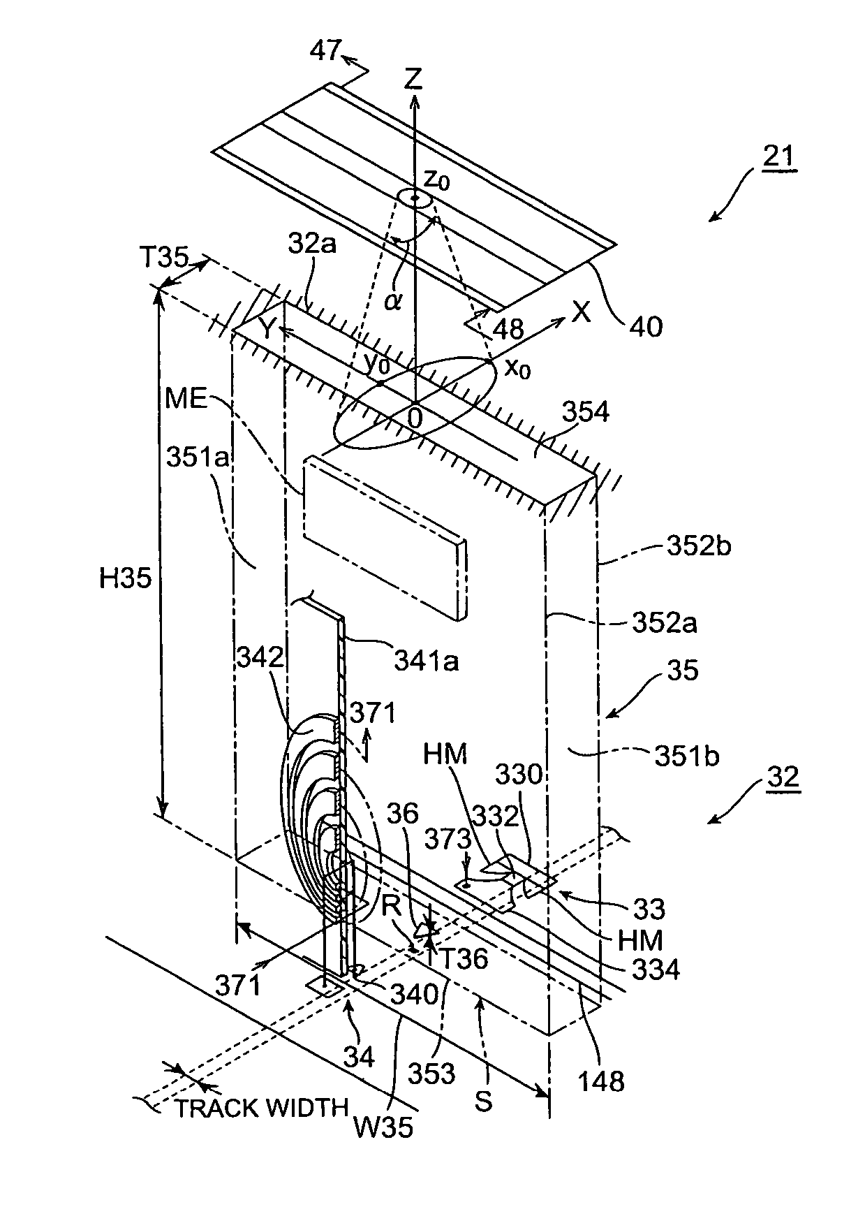
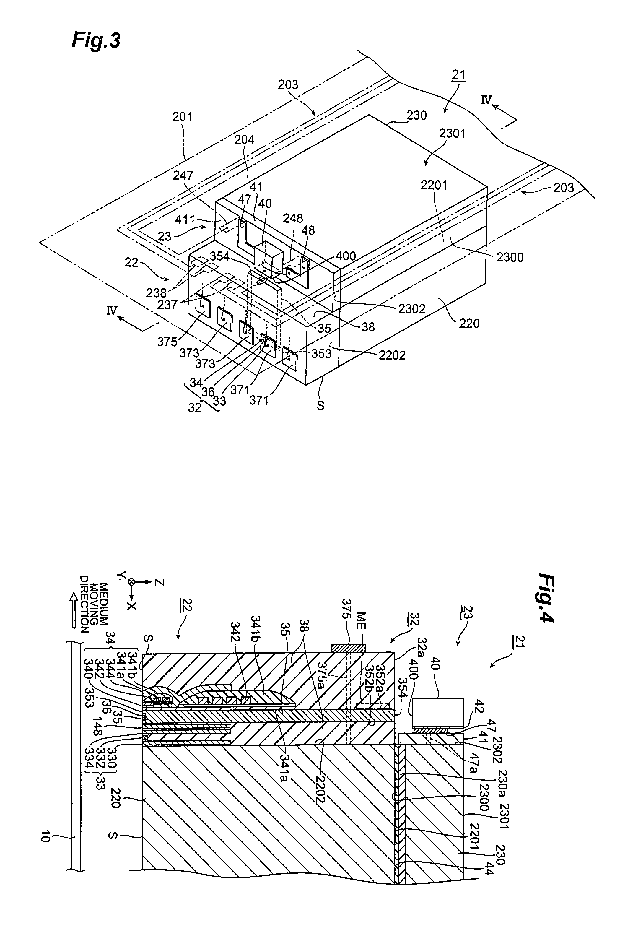
[0057]Embodiments for carrying out the present invention will be described below in detail with reference to the accompanying drawings. In each of the drawings the same elements will be denoted by the same reference numerals. It is also noted that the dimensional ratios in and between the constituent elements in the drawings are arbitrary, for easier understanding of the drawings.

(Hard Disk Drive)

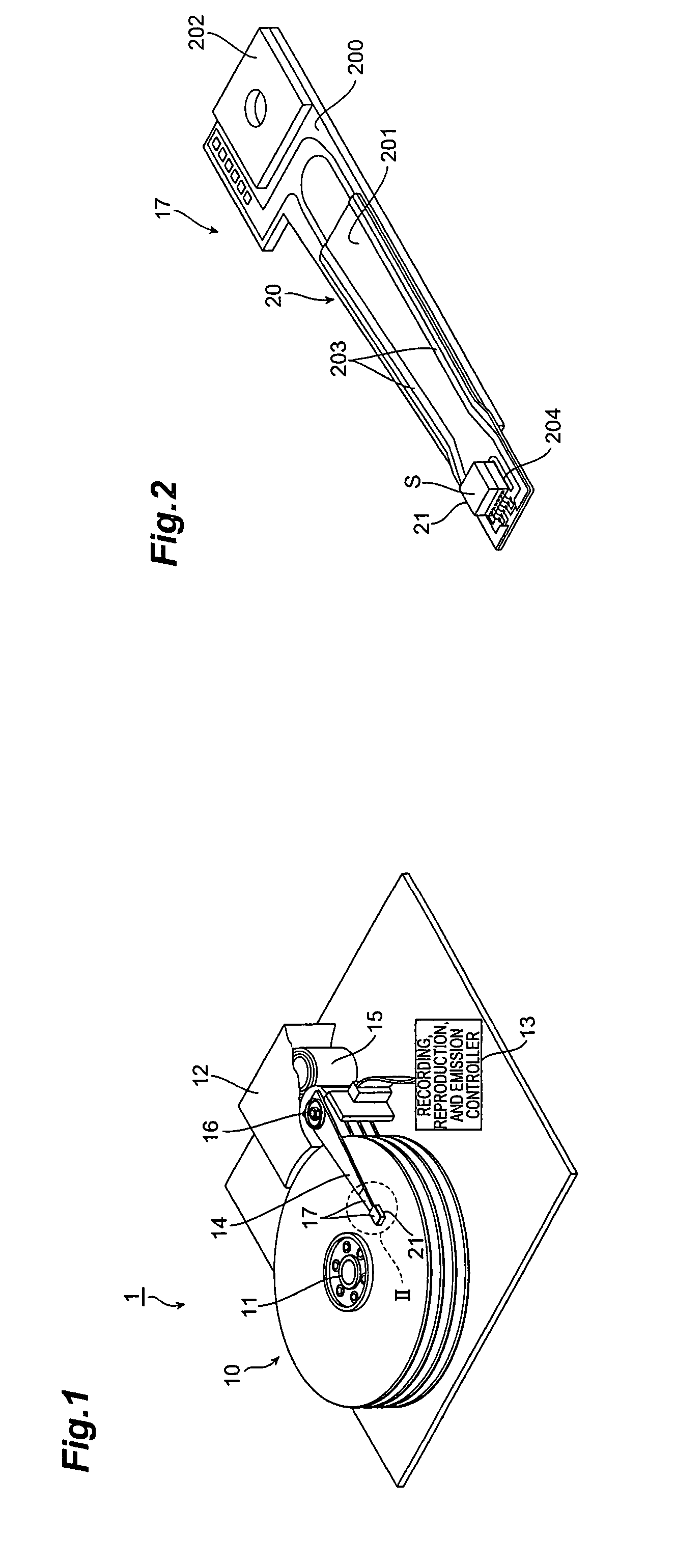
[0058]FIG. 1 is a perspective view of a hard disk drive according to an embodiment.

[0059]The hard disk drive 1 has magnetic disks 10 consisting of a plurality of magnetic recording media to rotate around a rotation shaft of spindle motor 11, an assembly carriage device 12 for positioning each thermally assisted magnetic head 21 on a track, and a recording, reproduction, and emission control circuit (control circuit) 13 for controlling writing and reading operations of each thermally assisted magnetic head 21 and for controlling a laser diode as a light source for emitting laser light for th...


PUM

PropertyMeasurementUnit
track widthaaaaaaaaaa
diameteraaaaaaaaaa
diameteraaaaaaaaaa

Abstract

A laser diode is fixed to a light source support substrate and a first surface of a slider substrate is fixed to a second surface of the light source support substrate; therefore, the slider substrate and the laser diode are kept in a fixed positional relation. Since the laser diode faces a light entrance face of a core, long-distance propagation of light as in the conventional technology does not occur, and light emitted from a light emitting element is guided well to a medium-facing surface while permitting some mounting error and coupling loss of light. A spot size w of a light intensity distribution along the X-axis in the XY plane including an incident-light centroid position on the light entrance face is set larger than a thickness of the core, whereby variation in incidence efficiency is well suppressed against positional deviation.

Description

BACKGROUND OF THE INVENTION[0001]1. Field of the Invention[0002]The present invention relates to a thermally assisted magnetic head for writing of signals by thermally assisted magnetic recording and to a head gimbal assembly (HGA) with this thermally assisted magnetic head, and a hard disk drive with this HGA.[0003]2. Related Background Art[0004]As the recording density of the hard disk drive increases, further improvement is demanded in the performance of the thin film magnetic head. The thin film magnetic head commonly used is a composite type thin film magnetic head of a structure in which a magnetic detecting element such as a magneto-resistive (MR) effect element and a magnetic recording element such as an electromagnetic coil element are stacked, and these elements are used to read and write data signals from and into a magnetic disk as a magnetic recording medium.[0005]In general, the magnetic recording medium is a kind of a discontinuous body of fine magnetic particles aggr...

Claims


Application Information

Patent Timeline
Patent Type & Authority Patents(United States)
IPC IPC(8): G11B11/105G11B11/10G11B7/125G11B7/135G11B5/02
CPCG11B5/02G11B5/314G11B2005/0021G11B2005/0005
Inventor SHIMAZAWA, KOJITANAKA, KOSUKEDOMON, TAKAAKI
Owner TDK CORPARATION
Why Eureka
Try Eureka