
Method for limiting signal and transmitter

a technology applied in the field of limiting signal and transmitter, can solve the problems of reducing the efficiency of amplifier and/or transmitter, limiting the obtainable maximum transmission power of power amplifiers, and high cost of power amplifiers with a broad linear operating rang

Inactive Publication Date: 2011-05-10
NOKIA TECH OY +1
View PDF32 Cites 2 Cited by
  • Summary
  • Abstract
  • Description
  • Claims
  • Application Information

AI Technical Summary

Benefits of technology

The patent describes a method for limiting signals in a transmitter at the chip level. The method involves determining a limiting signal from a transmissible signal filtered using a pulse shaping filter, and then using the limiting signal to filter the signal. This helps to reduce errors and improve the overall quality of the signal. The method can be implemented in a variety of ways, such as by determining the limiting signal from a combination of signals or by dividing the error signal onto different carriers. The technical effect of this patent is to provide a more efficient and effective way to limit signals in a transmitter at the chip level.

Problems solved by technology

In several data transmission systems, the linearity of a power amplifier limits the obtainable maximum transmission power, especially when the Peak-to-Average Ratio of a transmissible signal is high.
However, a problem arises, since back off reduces the efficiency of the amplifier and / or the transmitter.
Then again, the power amplifiers having a broad linear operating range are expensive and the efficiency thereof is very poor.
However, the prior art methods generally alter the signal in such a manner that in code division multiple access systems the orthogonality of different user-specific codes is no longer maintained.
Occasionally the power or amplitude of transmission cannot be limited in practice in order for the detection in the receiver of the subscriber device to be successful, since a multilevel modulation method is used, in which the symbols are placed so close to one another in a signal space diagram that even the slightest increase in noise causes an error in the detection.

Method used


Image

  • Method for limiting signal and transmitter
  • Method for limiting signal and transmitter
  • Method for limiting signal and transmitter

Examples


Embodiment Construction

[0028]The solution according to the invention is particularly applicable to WCDMA (Wide Band Code Division Multiple Access) radio systems, in which Direct Sequence (DS) technique is employed. Other applications may include satellite systems, military telecommunications systems and individual non-cellular networks. However, the solution of the invention is not restricted thereto.

[0029]In the following, the preferred embodiments of the invention are described in the UMTS (Universal Mobile Telephone System) system without restricting the invention thereto.

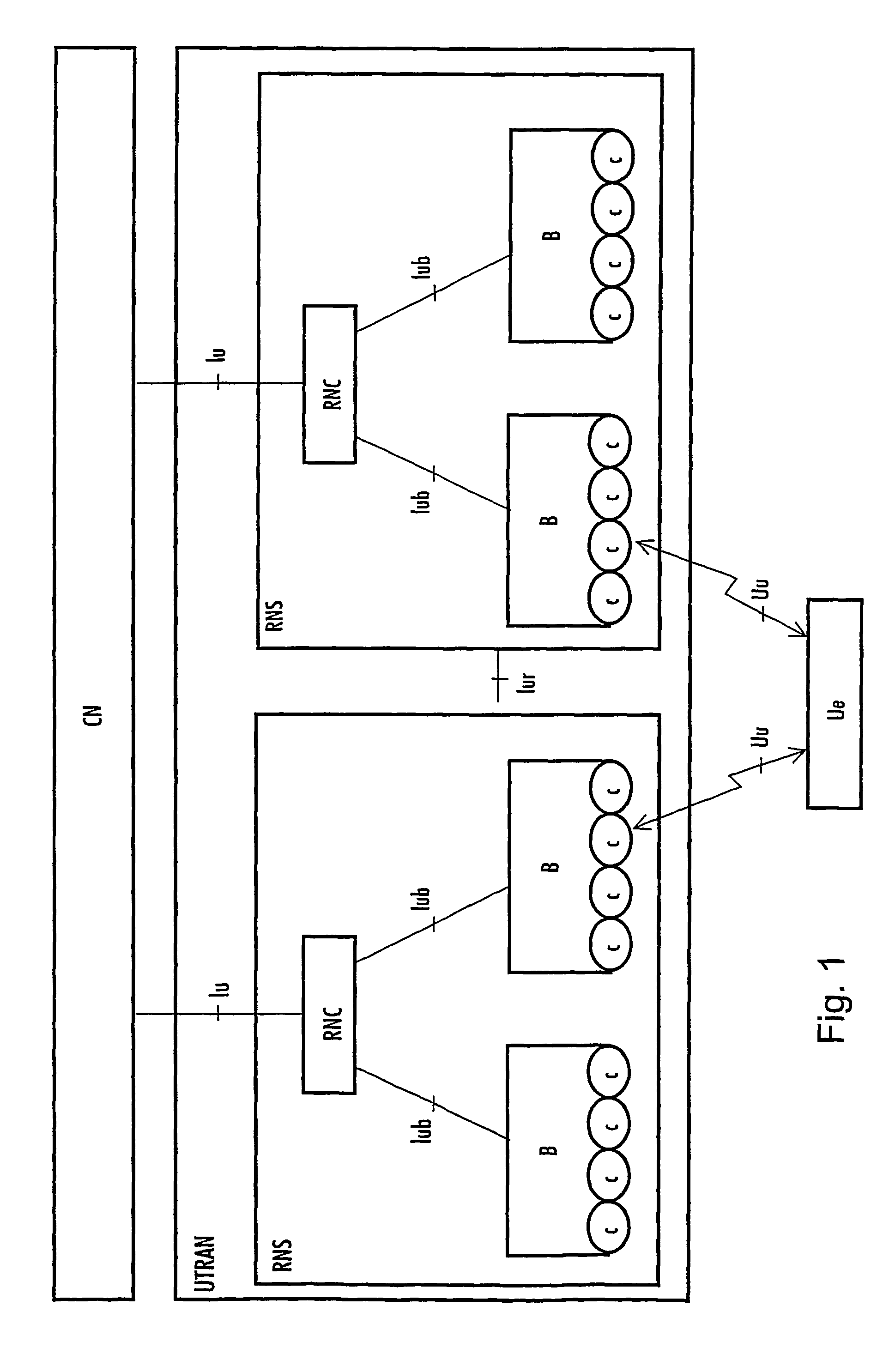
[0030]With reference to FIG. 1, the structure of a mobile communication system is explained by way of example. The main parts of the mobile communication system are a core network CN, a UMTS terrestrial radio access network UTRAN and user equipment UE. The interface between the CN and the UTRAN is referred to as Iu, and the air interface between the UTRAN and the UE is referred to as Uu.

[0031]The UTRAN comprises radio network subsyste...


PUM


Abstract

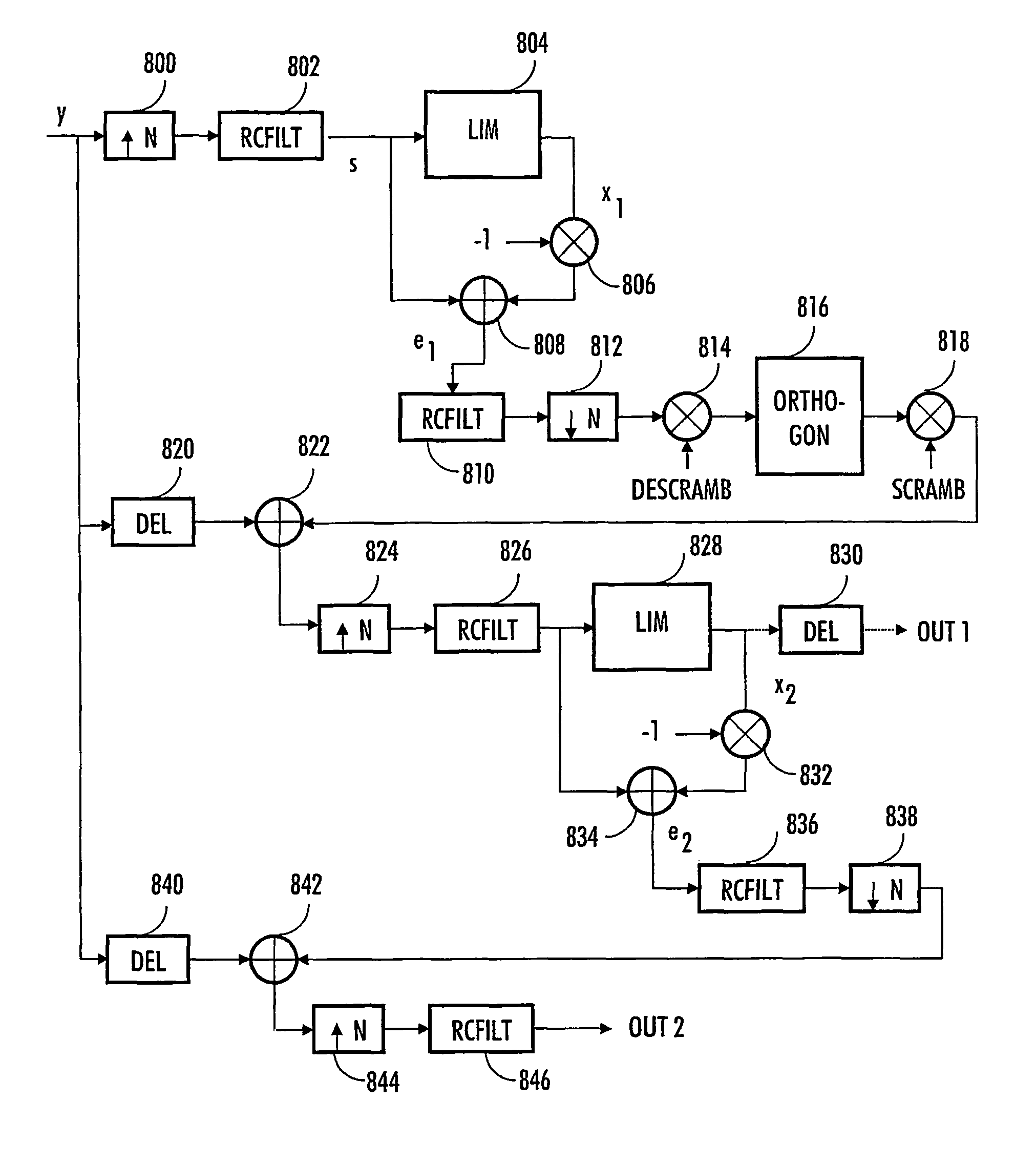
The invention relates to a method and a transmitter for limiting a signal at chip level. The transmitter limiting the signal at chip level comprises means (704) for determining a limiting signal from a transmissible signal filtered using a pulse shaping filter, the transmitter comprises means (704, 710, 712) for determining an error signal using the transmissible signal and the limiting signal, the transmitter comprises means (720) for generating a limited transmissible signal by reducing the error signal filtered using the filter matched to a chip pulse waveform from the transmissible signal and the transmitter comprises means (722, 724) for filtering the limited transmissible signal using the pulse shaping filter.

Description

FIELD[0001]The invention relates to a method for limiting power or amplitude values of a signal in a transmitter at chip level, and a transmitter.BACKGROUND[0002]In several data transmission systems, the linearity of a power amplifier limits the obtainable maximum transmission power, especially when the Peak-to-Average Ratio of a transmissible signal is high. In such a case, high power or amplitude values may temporarily occur in a signal to be fed into the power amplifier that have to be taken into account when the power amplifier is being dimensioned. In practice, this means that the input signal of the amplifier must be scaled to a lower power or amplitude level in order to fulfil the spectrum requirements of the data transmission system in use. What this method, referred to as back off, provides is that a signal to be amplified is located within an area, where the transmission function of the amplifier is more linear. However, a problem arises, since back off reduces the efficie...

Claims


Application Information

Patent Timeline
Patent Type & Authority Patents(United States)
IPC IPC(8): H04K1/02H04B1/707H04L27/26
CPCH04B1/70755H04L27/2624H04B2201/70706
Inventor PAJUKOSKI, KARI
Owner NOKIA TECH OY
Learn More