Engine control device

a control device and engine technology, applied in the direction of electrical control, engine testing, structural/machine measurement, etc., can solve the problems of time delay dl before the reference, difficulty in correcting the value of the crank counter, and difficulty in correctly controlling the operation of the engine, so as to avoid any error operation and avoid error operation

Inactive Publication Date: 2011-05-17
DENSO CORP
View PDF12 Cites 10 Cited by
  • Summary
  • Abstract
  • Description
  • Claims
  • Application Information

AI Technical Summary

Benefits of technology

[0020]It is an object of the present invention to provide an engine control device capable of avoiding errors when detecting a missing tooth location formed on a rotor of a crank shaft sensor, which is fixed to a crank shaft of an engine, and capable of suppressing incorrect adjustment of a counter value of a crank counter to count the number of crank signals of a pulse train transferred from a pickup coil in the crank shaft sensor, and thereby capable of correctly controlling the operation of the engine.
[0027]In the engine control device having the above configuration according to the present invention, the correct counter value of the crank counter when the missing tooth location detection means detects the missing tooth location is set as the missing tooth location counter set value. It is thereby possible to calculate a difference (as the crank counter difference value) between the counter value of the crank counter and the true counter value of the crank counter.
[0028]The missing tooth location detection verifying means verifies whether or not the detection result by the missing tooth location detection means is correct. That is, the missing tooth location detection verifying means verifies the detection result based on conditions other than the condition whether or not the first pulse interval division value is not less than the first judgment value. Using those conditions can increase the accuracy to detect the missing tooth location.
[0031]As described above, the engine control device according to the present invention avoids any error operation of detecting the missing tooth location of the crank shaft, and avoids error operation of adjusting the counter value of the crank counter.

Problems solved by technology

As a result, this makes it difficult to correctly control the operation of the engine.
However, realizing the method of detecting the missing tooth location causes a following problem.
However, because of executing the software program with a high priority rather than that of the missing tooth location detection, there can occur a time delay DL before the reference counter value is completely set into the crank counter (timing t12 shown in FIG. 5).
As described above, the conventional engine control device has the problem of it being difficult to adjust the value of the crank counter to the correct value corresponding to the actual crank shaft position.

Method used


Image

  • Engine control device
  • Engine control device
  • Engine control device

Examples


embodiment

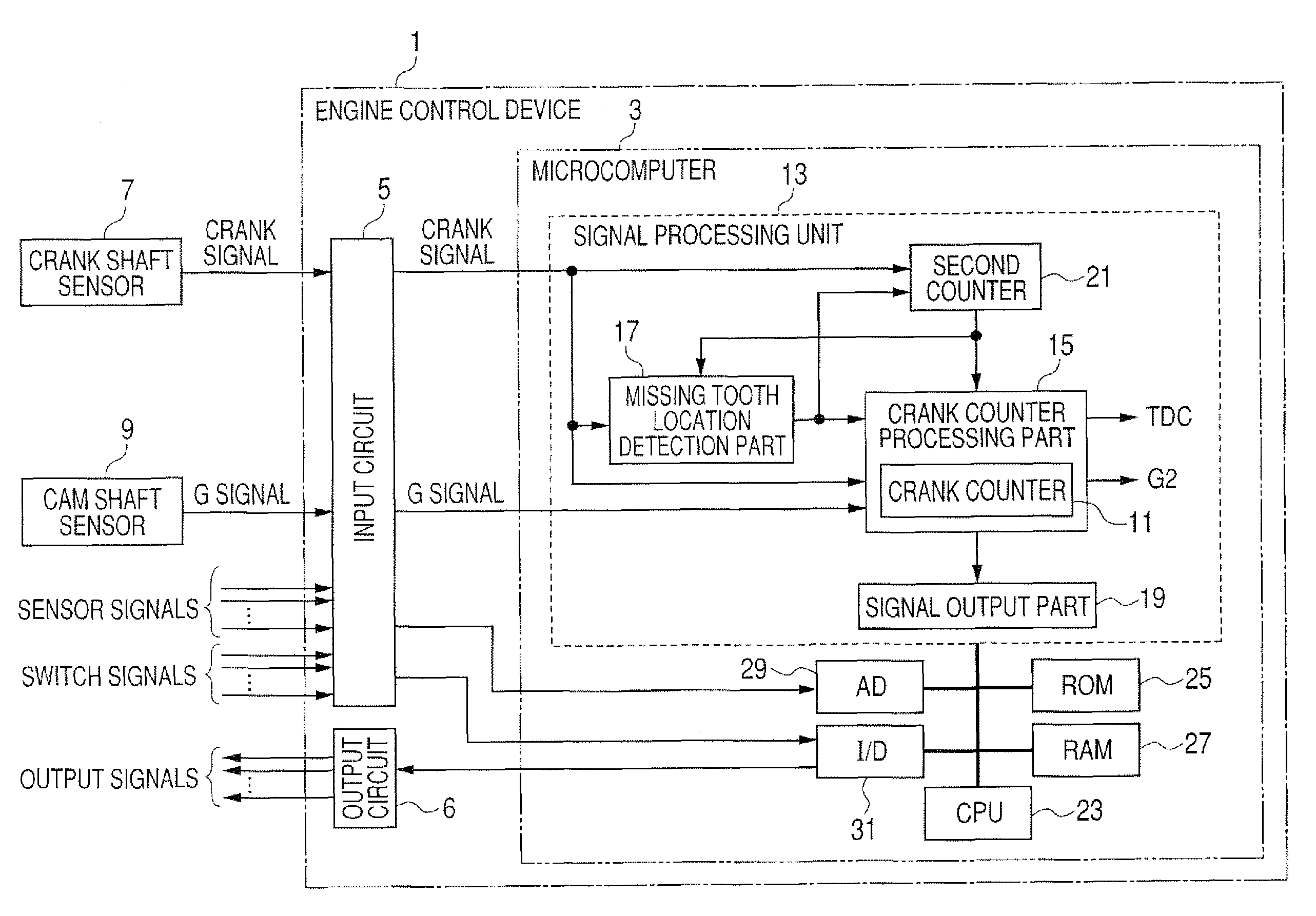
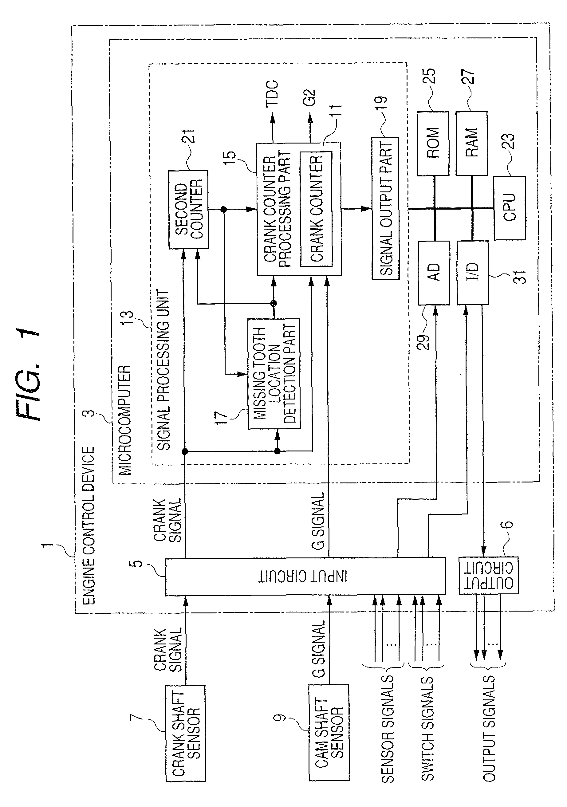
[0043]A description will be given of the engine control device 1 according to an embodiment of the present invention with reference to FIG. 1 to FIG. 6.

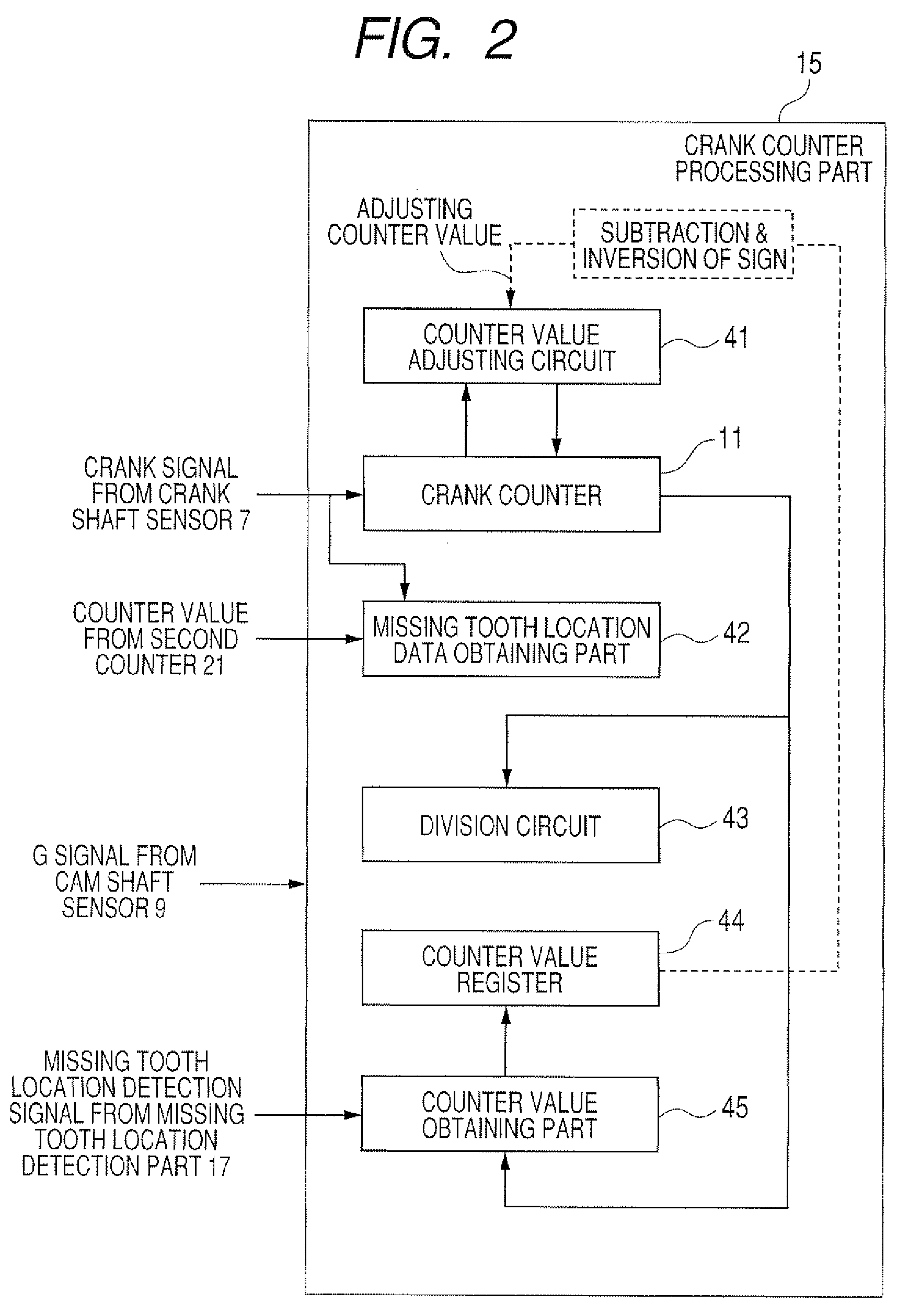
[0044]FIG. 1 is a diagram showing an entire configuration of the engine control device 1 according to the embodiment of the present invention. In particular, FIG. 2 shows a main configuration of a crank counter processing part 15 in the engine control device 1. FIG. 3 schematically shows a configuration of a counter value adjusting circuit 41 in the crank counter processing part 15 of the engine control device 1. FIG. 4 schematically shows a configuration of a missing tooth location data obtaining part 42 in the crank counter processing part 15 of the engine control device 1. FIG. 5 is a flow chart showing a process of calculating an adjusted counter value for a crank counter 11 in the crank counter processing part 15. FIG. 6 is a timing chart explaining a process of rewriting the counter value of the crank counter 11 in the crank co...


PUM


Abstract

In an engine control device, when a missing-tooth location K formed on a rotor of a crank shaft sensor fixed to a crank shaft of an engine is detected at timing t1 under the condition T3 ≧2.4×pulse interval T4, it is checked whether or not the detection result is correct based on pulse intervals T0 to T5. When the detection result is correct, the difference (an adjusting counter value) between a counter-value of a crank counter at the missing-tooth location K detection timing and a correct value at the detection timing of the missing-tooth location K is calculated. The device calculates an adjusted counter-value based on an adjusting counter-value, the current counter-value of the crank counter, and a value (+1) set in advance based on the rewriting timing. The crank counter is replaced with the adjusted counter-value at a first rising-edge of the crank signal.

Description

CROSS-REFERENCE TO RELATED APPLICATION[0001]This application is related to and claims priority from Japanese Patent Application No. 2008-188592 filed on Jul. 22, 2008, the contents of which are hereby incorporated by reference.BACKGROUND OF THE INVENTION[0002]1. Field of the Invention[0003]The present invention relates to an engine control device for controlling the operation of an engine.[0004]2. Description of the Related Art[0005]A conventional engine control device detects the crank angle of a crank shaft based on a crank pulse signal (or a crank signal) transferred from a crank shaft sensor and a cylinder discriminating signal (G pulse signal) transferred from a cam shaft sensor. The engine control device performs a fuel injection control and an ignition timing control for an internal combustion engine. The crank shaft sensor generates crank pulse signals based on a rotation of the crank shaft of the engine. The cam shaft sensor generates the cylinder discriminating signal base...

Claims


Application Information

Patent Timeline
Patent Type & Authority Patents(United States)
IPC IPC(8): G01M15/06
CPCF02D41/009F02D41/222
Inventor TAKEUCHI, YOSHIHARU
Owner DENSO CORP
Why Eureka
Try Eureka