Electrical connector assembly and method

a technology of electrical connectors and connector assemblies, applied in the direction of coupling device connections, coupling device details, contact members penetrating/cutting insulation/cable strands, etc., can solve the problems of inability to accurately locate the contact point of insulation displacement with the conductor in the wire, cumbersome two-step procedures, complex and inconvenient,

Inactive Publication Date: 2011-05-17
PHOENIX CONTACT DEVMENT & MFG
View PDF12 Cites 11 Cited by
  • Summary
  • Abstract
  • Description
  • Claims
  • Application Information

AI Technical Summary

Benefits of technology

[0006]The use of wire carriers each holding two wires prevents the build up tolerances between the contact members and the wire passages holding the wires and assures that the insulation displacement contact members reliably engage the conductors in the wires held in the passages.
[0008]The electrical connector assembly is very compact, allowing close spacing of the insulation displacement contact members in the base and close spacing of the wire passages in the carriers. This reduces the real estate required for mounting the assembly on a circuit board or other member and reduces manufacturing cost.
[0009]The assembly may have one or more wire carriers. The wire carriers can be identical. This reduces manufacturing cost for the assembly. Alternatively, the assembly may have two or more wire carriers which receive a different number of wires for forming electrical connections. For instance, the assembly may have one two-wire carrier and one three-wire carrier. The wire carriers can receive different diameter wires. Each carrier can be closed manually, without the necessity of using a closing tool.
[0010]The wire carrier can be rotated or translated into the base. When rotated into the base, the carrier moves along a cam which moves the carrier forward against a latch to flex the latch and, when the wire carrier is fully rotated into the base, to position the carrier against the latch to increase the overlap between the latch and the carrier and strengthen the latched connection holding the carrier in the base.
[0011]The insulation displacement contacts used in the electrical connector assembly are formed from a strip of thin metal and have three upwardly extending pierce points. The tips of two of the pierce points are located on opposite sides of the strip and, during closing of the assembly, slide along the opposite walls of a contact slot in the carrier to engage the conductor of the wire located in a wire passage above the slot. The third pierce point has a tip located midway between the sides of the strip. The three laterally spaced tips increases the likelihood that the tips will engage the stranded conductor in the wire to form an electrical connection with the conductor.
[0012]The three pierce points have a thickness at the base of the pierce points equal to the thickness of the strip and a reduced thickness along the height of the points to the tips. The tips are inserted into the stranded conductor in the wire and, with further insertion, spread the conductors apart to increase the normal forces between the tip and the strands of wire. The wires are confined in the wire passage. The increased normal forces between the sides and edges of the tips and the strands in the conductor improves electrical connections with the conductor.

Problems solved by technology

The two-step procedure is cumbersome, complex and inconvenient.
However, a disadvantage of insulation displacement connections for small wires in conventional electrical connector assemblies is the inability of accurately locating the insulation displacement contact point with the conductor in the wire during closing of the assembly when a number of connections are established at the same time.
This alignment problem arises because of accumulated molding tolerances in the parts of the connector which support the wires and the insulation displacement contact members.

Method used


Image

  • Electrical connector assembly and method
  • Electrical connector assembly and method
  • Electrical connector assembly and method

Examples


first embodiment

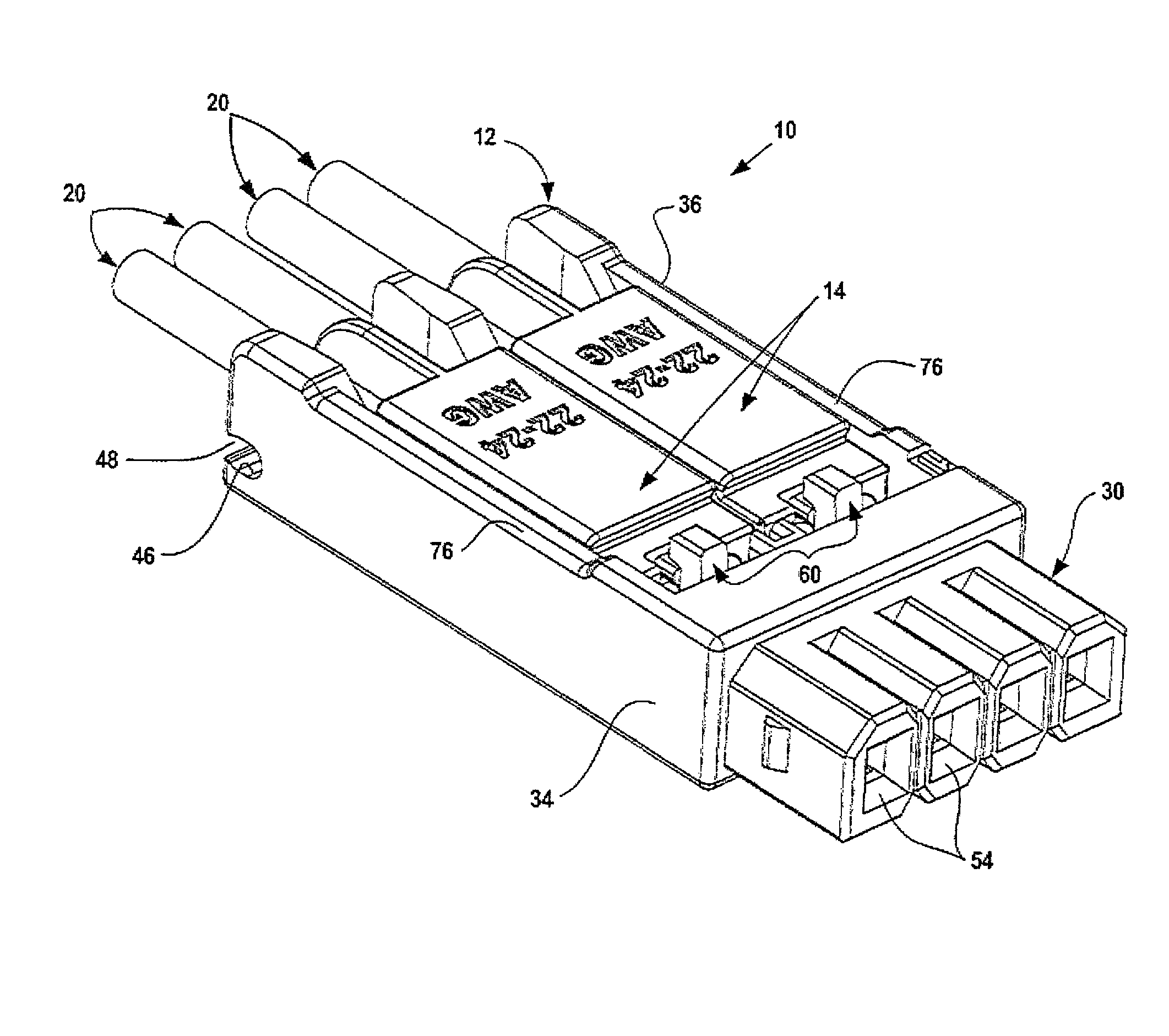
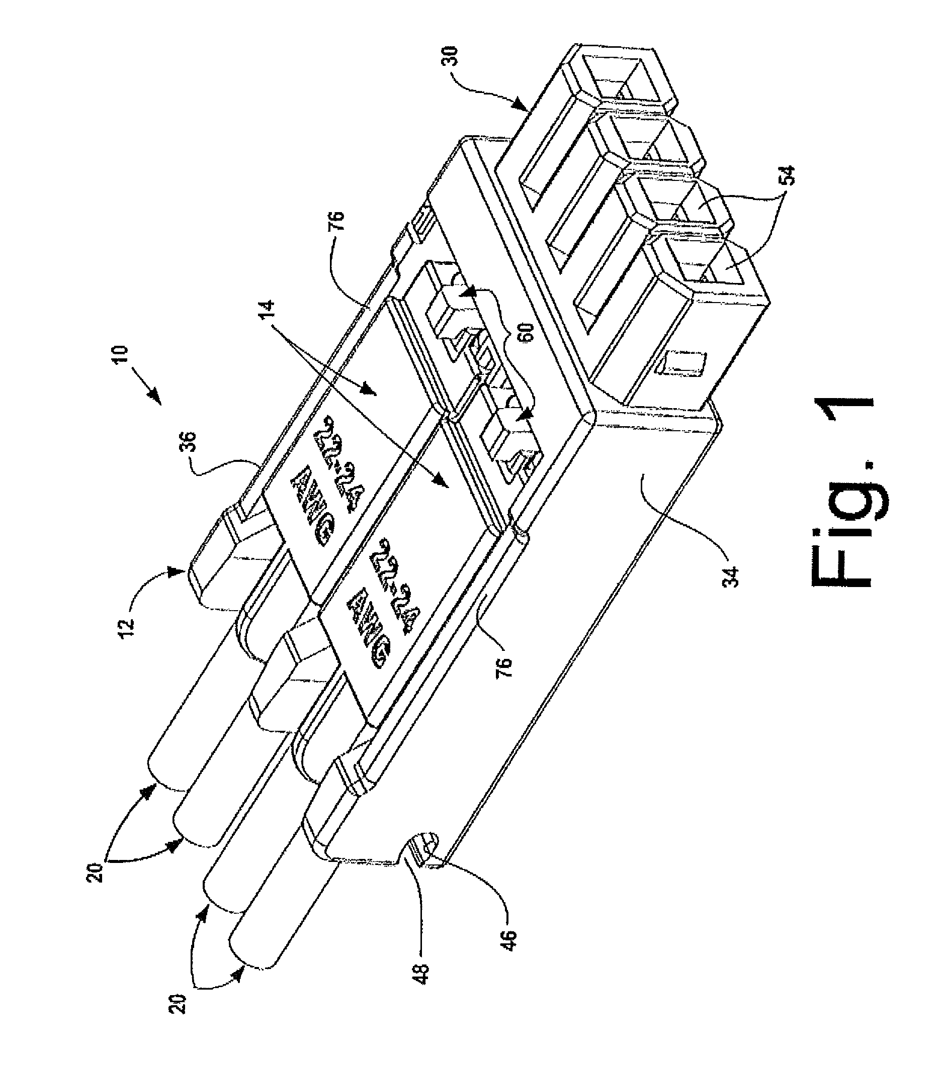
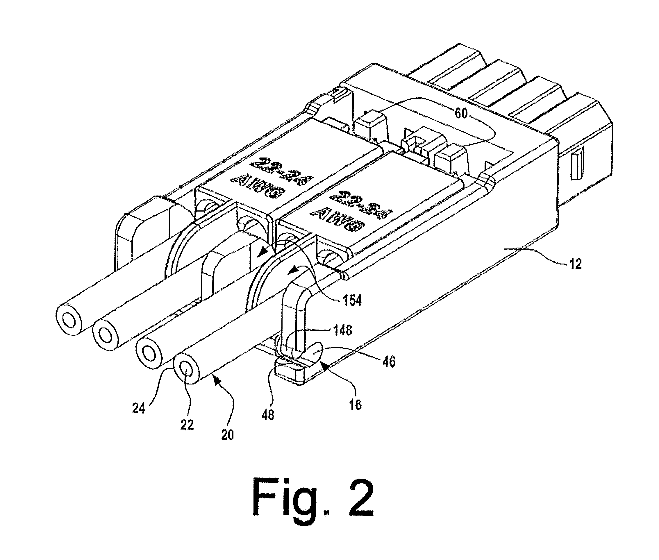
[0034 electrical connector assembly 10 is illustrated in FIGS. 1-20 of the drawings. Assembly 10 includes a molded plastic base 12 and two molded plastic wire carriers 14 pivotally mounted on the rear end of the base at hinge connections 16. Four metal contact members 18 are mounted in base 12 for forming redundant insulation displacement electrical connections with wires 20 inserted in carriers 14. Two wires are inserted into each wire carrier.

[0035]Wires 20 typically have small diameters and small central stranded metal conductors 22 surrounded by an insulating sheath 24, which may be made of PVC. The electrical connector assembly 10 shown in FIG. 1 forms reliable electrical connections with AWG 22 or AWG 24 wires 20. FIG. 14 illustrates an alternative wire carrier 174 for making connections with AWG 26 wires.

[0036]AWG 22-26 wires are very small. AWG 22 wire has a diameter of 1.6 mm and a stranded conductor having a diameter of 0.65 mm. AWG 24 wire has a diameter of 1.4 mm and a s...

second embodiment

[0084]FIGS. 21-28 illustrate a second embodiment electrical connector assembly 200 related to assembly 10 having a molded dielectric base 202 and molded dielectric wire carrier 204. The wire carrier 204 is pushed straight down into or translated into the base to establish insulation displacement electrical connections. Assembly 200 uses components identical to components of assembly 10. Reference numbers describing components of assembly 10 which are used in assembly 200 are identified using the previously introduced reference numbers.

[0085]Base 202 is similar to base 12 and includes bottom wall 28, slots 56 in the bottom wall, side walls 34 and 36 and contact housing 30 extending across the front end of the base. Metal contact members 18 are fitted in slots 56 with contact elements 90 in housing contact chambers 50.

[0086]Wire carrier 204 includes a rectangular molded plastic body 206 with four spaced wire passages 140 extending from the rear to the front of the body. Cylindrical wi...


PUM


Abstract

An electrical connector assembly for forming insulation displacement connections with conductors in small wires includes a wire carrier and a base. Pierce points on the base are slid along opposed walls in a slot in the carrier to align small tips on the ends of the pierce points to form electrical connections with a conductor in a wire in the carrier. The connections are located inwardly of the slot walls.

Description

FIELD OF THE INVENTION[0001]The invention relates to electrical connector assemblies for forming insulation displacement connections with insulated wires and to related methods.DESCRIPTION OF THE PRIOR ART[0002]Contact members are individually attached to the ends of small diameter wires in the field using special tooling to strip the insulation from the end of the wire and then crimp part of a contact member around the exposed conductor. After the contact member is crimped to the wire, the member is placed in an assembly to position the member for establishing an electrical connection with a mating part. The two-step procedure is cumbersome, complex and inconvenient.[0003]Sometimes, special tooling is used to strip insulation from a number of wires simultaneously and then simultaneously crimp contact members onto the stripped ends of the wires. In some cases different diameter wires must be attached to contacts at the same time. Specialized tooling is required.[0004]Insulation disp...

Claims


Application Information

Patent Timeline
Patent Type & Authority Patents(United States)
IPC IPC(8): H01R4/24
CPCH01R4/2404H01R23/10H01R13/506H01R13/112H01R24/28H01R2107/00
Inventor HUSS, JR., JOHN PHILLIPGESKE, RALFSCHULTE, HANS-HILMARFREUND, KARSTENSONDERER, MARKUSBEIER, THOMAS
Owner PHOENIX CONTACT DEVMENT & MFG
Why Eureka
Try Eureka