Superconducting cable

a superconducting cable and cable technology, applied in the direction of superconducting magnets/coils, insulated conductors, cables, etc., can solve the problem of excessive temperature rise, reduce the intruder's heat, reduce the cable diameter, and improve the dc voltage resistance.

Inactive Publication Date: 2011-05-17
SUMITOMO ELECTRIC IND LTD
View PDF8 Cites 9 Cited by
  • Summary
  • Abstract
  • Description
  • Claims
  • Application Information

AI Technical Summary

Benefits of technology

[0048]A superconducting cable of the present invention having the above-described structure has a further decreased cable diameter. Nevertheless, it can be used for bipolar transmission with one cable. In addition, even when one of the poles creates an abnormal condition, the transmission can be performed by switching from the bipolar transmission to unipolar transmission. Moreover, a superconducting cable of the present invention is provided with a coolant-circulating pipe without increasing the cable diameter. This structure can decrease the intruding heat.
[0049]In addition, in the core provided in a superconducting cable of the present invention, by performing the ρ grading in the insulating layer, the thicknesswise distribution of the DC electric field can be flattened throughout the insulating layer. As a result, the DC voltage-withstanding property is improved, and consequently the thickness of the insulating layer can be decreased. Therefore, the cable diameter can be further decreased. In addition to the ρ grading, by providing an insulating layer having high ∈ in the vicinity of the superconducting conductor layer, the impulse voltage-withstanding property can also be improved in addition to the above-described improvement in the DC voltage-withstanding property. In particular, by structuring the insulating layer in such a way that as its radial position moves toward the innermost portion, the ∈ increases, and as the radial position moves toward the outermost portion, the ∈ decreases, a superconducting cable of the pre-sent invention can be a cable also having an excellent AC electric property. Therefore, a superconducting cable of the present invention can not only be suitably used for both of the DC transmission and AC transmission but also be suitably used during a transient period in which the transmission system is switched between AC and DC.

Problems solved by technology

When AC transmission is performed by using the above-described superconducting cable, not only is AC loss caused due to the inductance but also current at the time of the short circuiting is large, so that the temperature may rise excessively due to the loss at that moment.

Method used


Image

  • Superconducting cable
  • Superconducting cable
  • Superconducting cable

Examples


example 1

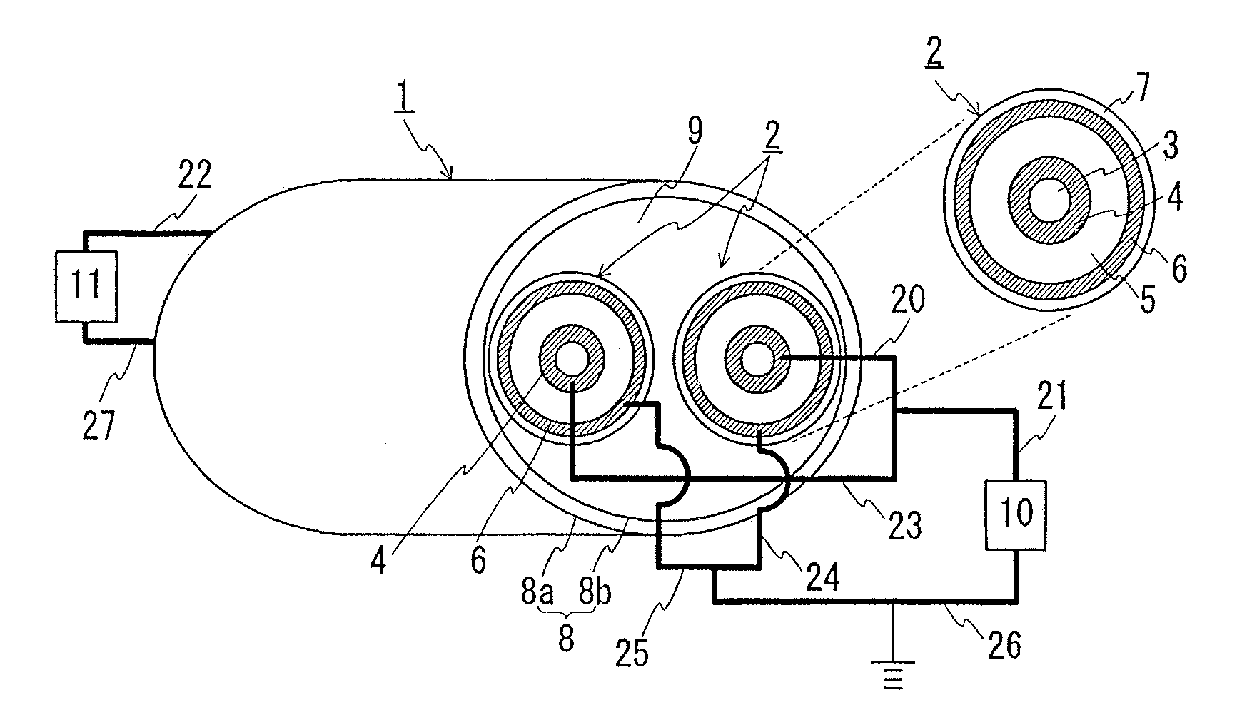
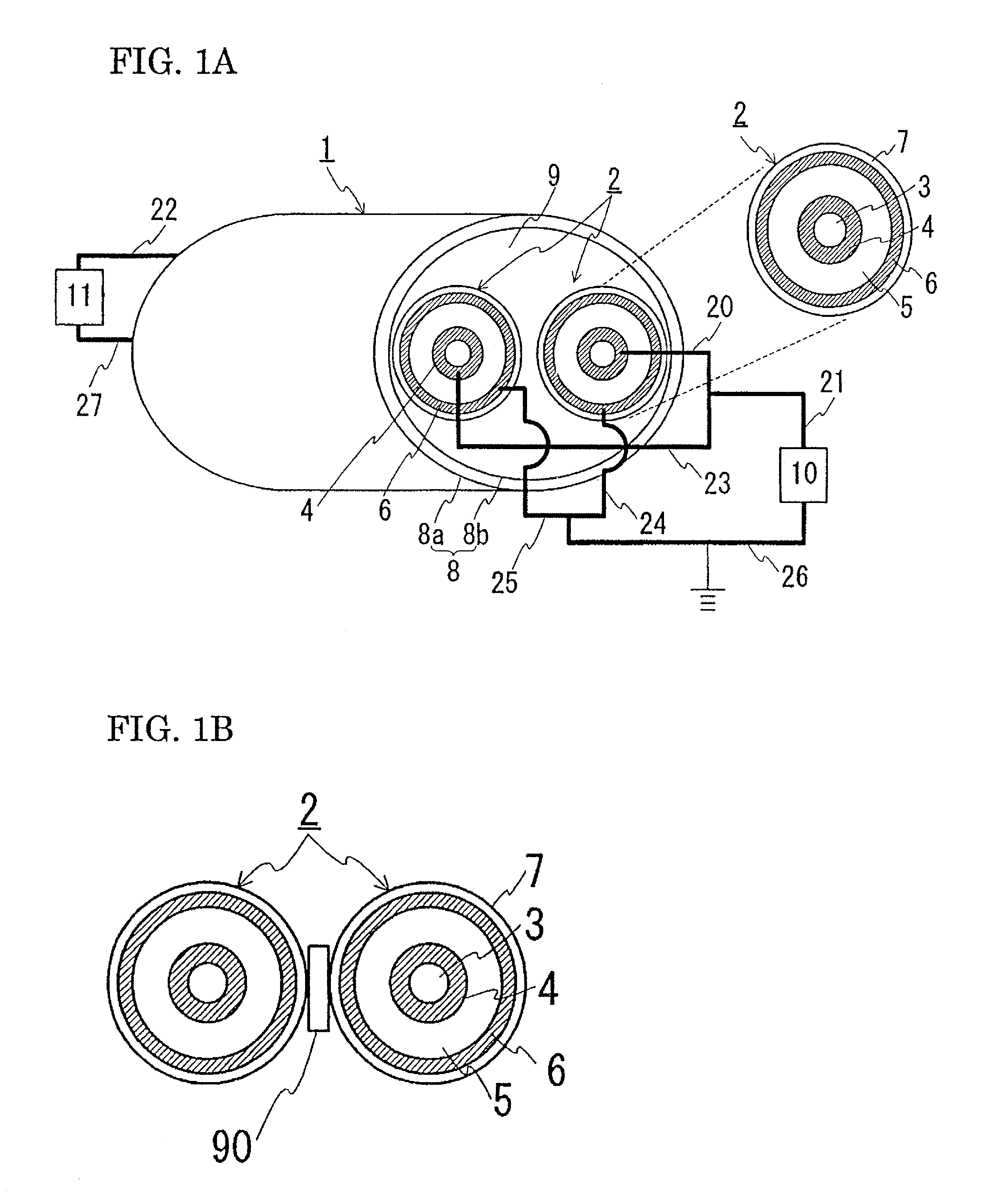
[0051]FIG. 1(A) is a schematic configuration diagram showing a state in which a DC transmission line for unipolar transmission is constructed by using a superconducting cable of the present invention. (B) is a schematic cross-sectional view showing a state in which a spacer is placed between the cable cores in the superconducting cable. In the following drawing, the same sign represents the same item. A superconducting cable 1 has a structure in which two cable cores 2, each of which has a superconducting conductor layer 4 and an outer superconducting layer 6 both made of a superconducting material, are twisted together and housed in a heat-insulated pipe 8. Each of the cable cores 2 is provided with a former 3, the superconducting conductor layer 4, an insulating layer 5, the outer superconducting layer 6, and a protecting layer 7 in this order from the center.

[0052]In this example, the superconducting conductor layer 4 and the outer superconducting layer 6 were formed by using Bi-...

example 2

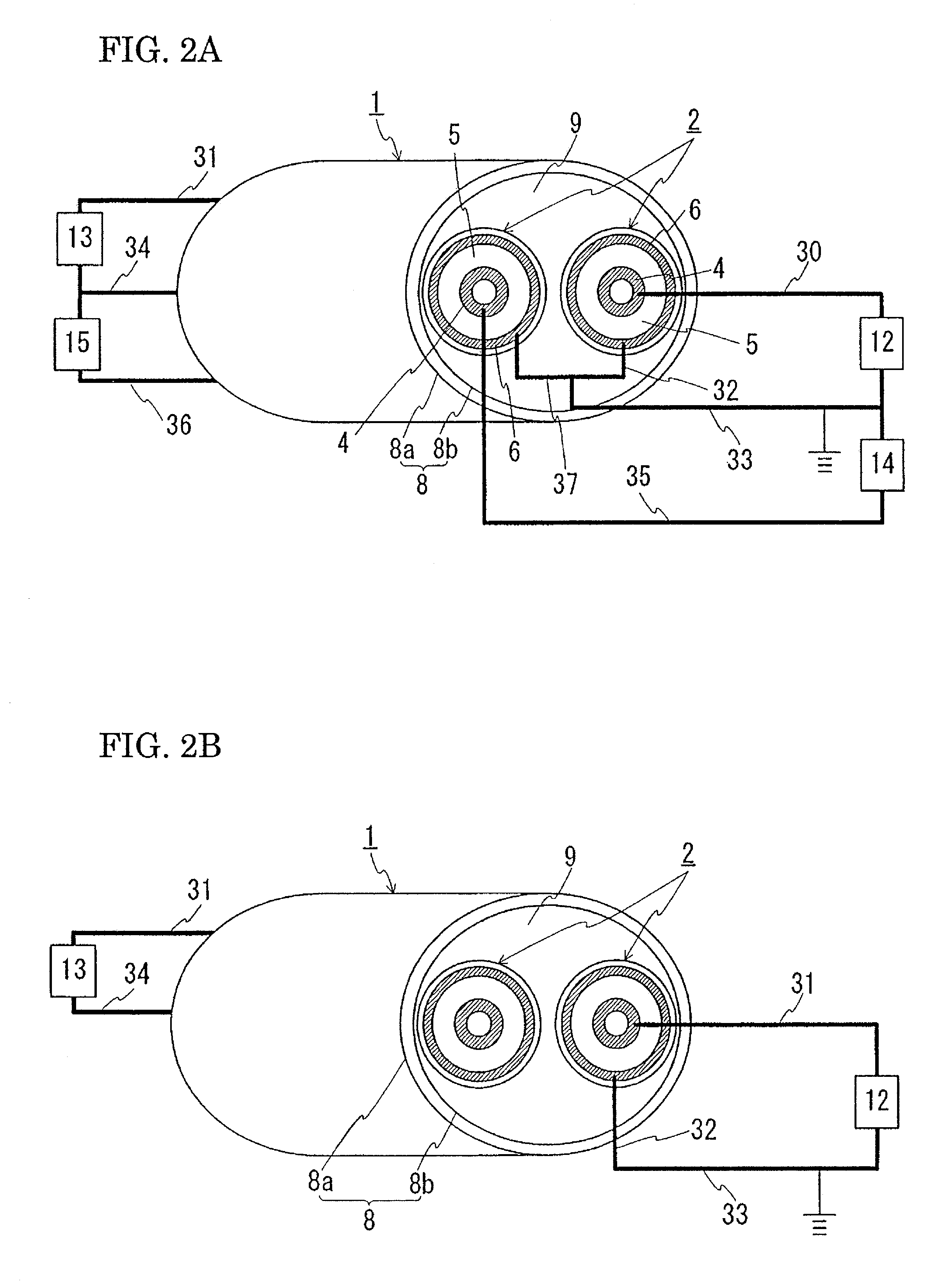
[0056]Next, the case where a bipolar transmission is performed is explained. FIG. 2(A) is a schematic configuration diagram showing a state in which a DC transmission line for bipolar transmission is constructed by using a superconducting cable of the present invention. FIG. 2(B) is a schematic configuration diagram showing a state in which a DC transmission line for unipolar transmission is constructed by using the superconducting conductor layer and outer superconducting layer of one of the cores. The superconducting cable 1 used in Example 1 can also be used for bipolar transmission. To perform the bipolar transmission, it is recommendable to construct a transmission line as shown in FIG. 2(A). More specifically, one end of the superconducting conductor layer 4 provided in one of the cores 2 (in FIG. 2(A), the core 2 at the right) is connected to a DC-AC converter 12, which is connected to an AC system (not shown), through a lead 30. The other end of the same superconducting cond...

example 3

[0066]Next, an explanation is given to a structure provided with both an outward channel of the coolant and a return channel of the coolant. FIG. 3 is a schematic cross-sectional view showing a superconducting cable of the present invention formed by twisting together two cable cores and coolant-circulating pipes. In the above-described Examples 1 and 2, an explanation is given to a structure in which the inside of the inner pipe of the heat-insulated pipe is used as a coolant channel. However, as shown in FIG. 3, coolant-circulating pipes 40 may be provided separately so that a space 9 in the inner pipe can be used as an outward channel of the coolant and so that the inside of the coolant-circulating pipes 40 can be used as a return channel of the coolant. When the outward and return channels of the coolant are provided as described above, the intruding heat can be decreased.

[0067]In this example, two coolant-circulating pipes 40 were prepared to form a structure in which two cable...


PUM

PropertyMeasurementUnit
diameteraaaaaaaaaa
diameteraaaaaaaaaa
thicknessaaaaaaaaaa

Abstract

A superconducting cable has a further decreased diameter, and a DC transmission system incorporates the cable. The superconducting cable has a structure in which two cable cores, each having a superconducting conductor layer and an outer superconducting layer, are twisted together and housed in a heat-insulated pipe. Each cable core has a former, superconducting conductor layer, insulating layer, outer superconducting layer, and a protecting layer in this order from the center. In unipolar transmission, the superconducting conductor layers of both cores are used as the outward line and the outer superconducting layers of both cores as the return line. In bipolar transmission, the superconducting conductor layer of one core is used for the transmission for the positive pole, the superconducting conductor layer of the other core is used for the transmission for the negative pole, and the outer superconducting layers of both cores are used as the neutral-line layers.

Description

TECHNICAL FIELD[0001]The present invention relates to a superconducting cable formed by twisting a plurality of cable cores together and to a DC transmission system incorporating the superconducting cable. The present invention particularly relates to a superconducting cable that can further reduce its diameter.BACKGROUND ART[0002]As an AC superconducting cable, a three-core-twisted-type cable is commonly known that is formed by twisting three cable cores together. FIG. 4 is a cross-sectional view of a three-core-twisted-type cable for the three-phase AC use. A superconducting cable 100 has a structure in which three cable cores 102 are twisted together and housed in a heat-insulated pipe 101. The heat-insulated pipe 101 has a dual-pipe structure composed of an outer pipe 101a and an inner pipe 101b, between which a heat-insulating material (not shown) is placed. The space between the outer pipe 101a and the inner pipe 101b is evacuated in vacuum. An anticorrosion covering 104 is pr...

Claims


Application Information

Patent Timeline
Patent Type & Authority Patents(United States)
IPC IPC(8): H01B12/00
CPCH01B12/06Y02E40/642Y02E40/60H01B12/08H01B12/16
Inventor HIROSE, MASAYUKI
Owner SUMITOMO ELECTRIC IND LTD
Why Eureka
Try Eureka