Optical encoder and electronic equipment

a technology of optical encoder and electronic equipment, applied in the direction of converting sensor output optically, instruments, material analysis, etc., can solve the problems of preventing accurate detection of position and increasing cost, and achieve the effect of low cost and sufficient precision

Inactive Publication Date: 2011-05-17
SHARP KK
View PDF20 Cites 10 Cited by
  • Summary
  • Abstract
  • Description
  • Claims
  • Application Information

AI Technical Summary

Benefits of technology

[0013]Accordingly, an object of the present invention is to provide an optical encoder capable of obtaining movement information and reference position information with sufficient precision at low cost.

Problems solved by technology

Thus, in the method for obtaining an index channel signal by placing the index track away from the incremental track, not only an optical area to use is widened, but also it is necessary to produce parallel beams corresponding to the wide optical area as well as to secure a light receiving area, which results in cost increase.
However, in JP 2003-294494 A, the light receiving surface areas of the photodiodes ZPD 1 to 4 for origin detection are different from the light receiving surface areas of photodiodes ZBPD 1 to 4 for non-origin detection, and therefore even with correction performed, variations in light receiving amount and the correction is not always correlated, which may prevent accurate detection of the position of the origin.

Method used


Image

  • Optical encoder and electronic equipment
  • Optical encoder and electronic equipment
  • Optical encoder and electronic equipment

Examples


first embodiment

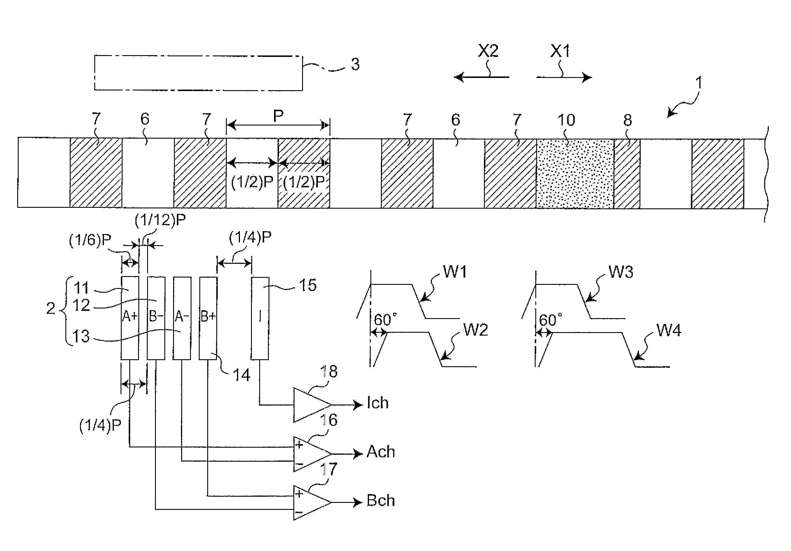
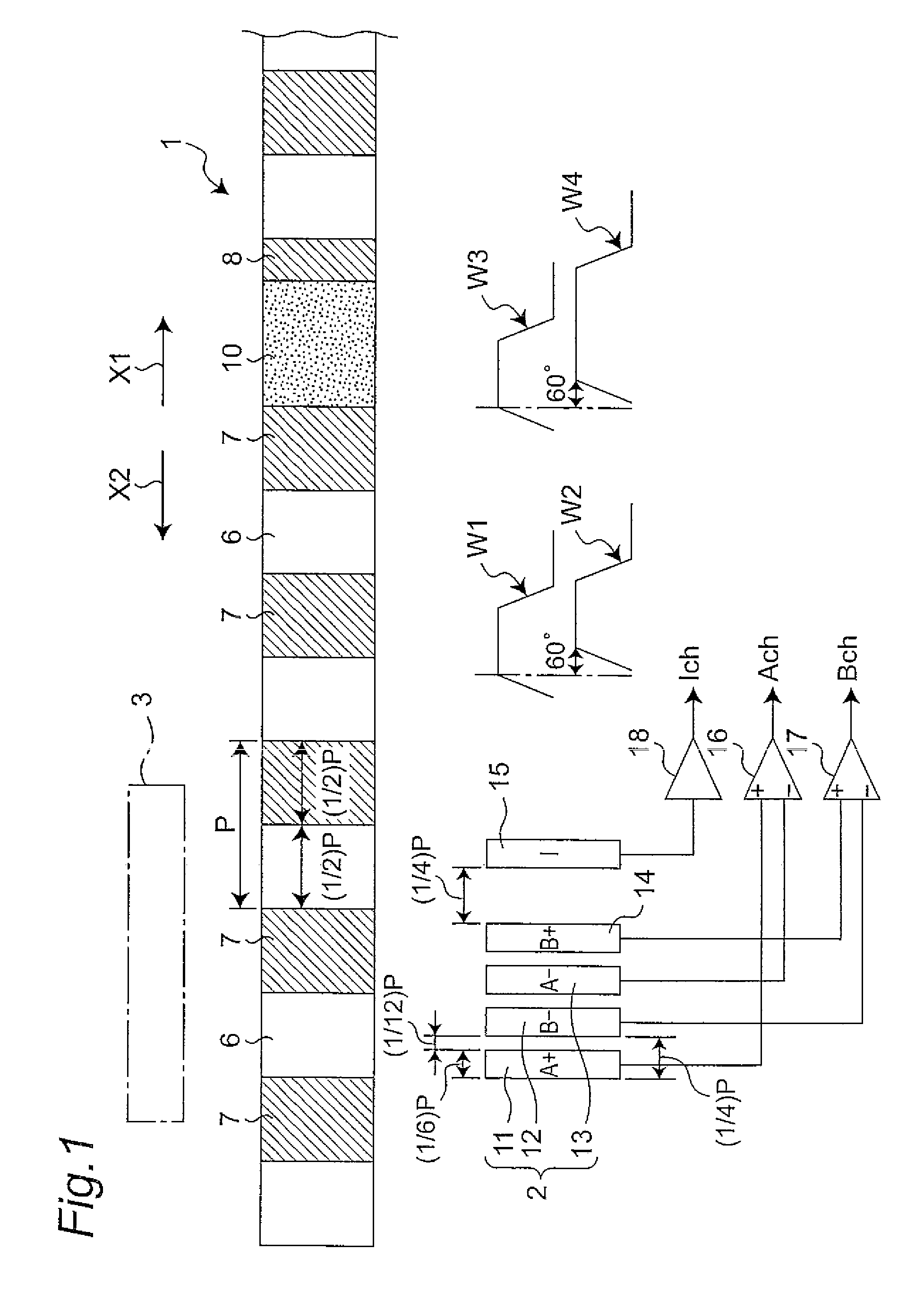
[0096]FIG. 1 shows an optical encoder in a first embodiment of the invention. The first embodiment is composed of a moving object 1, a light receiving section 2, and a light emitting section 3. The light emitting section 3 is constituted of light emitting elements such as LEDs (Light Emitting diodes). The light receiving section 2 has five light receiving elements 11 to 15. The moving object 1 is movable in the direction shown by arrow X1 or X2, with a light-ON section 6 and a light-OFF section 7 being alternately arranged in the moving direction. The moving object 1 has an index pattern section 10 interposed in between the light-OFF section 7 and the light-OFF section 8 in the moving direction. The light-OFF section 8 has a moving direction size (width size) shorter than that of the light-OFF section 7. The light-ON section 6 and the index pattern section 10 pass the light beam from the light emitting section 3 to the light receiving section 2 side, whereas the light-OFF section 8 ...

second embodiment

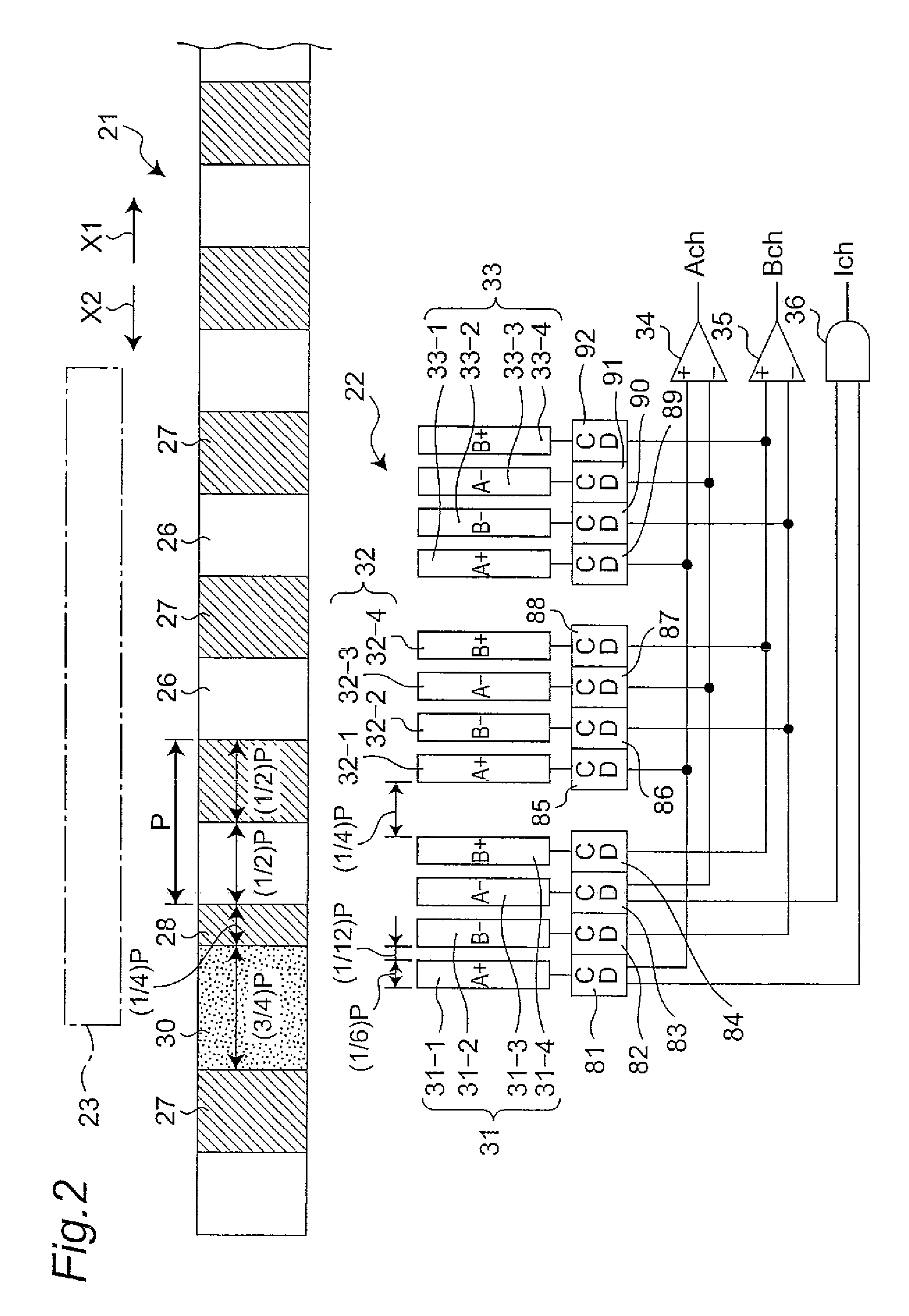
[0105]FIG. 2 shows an optical encoder in a second embodiment of the invention. The second embodiment is composed of a moving object 21, a light receiving section 22, and a light emitting section 23. The moving object 21 is movable in the direction shown by arrow X1 or X2, with a light-ON section 26 and a light-OFF section 27 being alternately arranged in the moving direction. The moving object 21 has an index pattern section 30 interposed in between the light-OFF section 27 and the light-OFF section 28 in the moving direction. The light-OFF section 28 has a moving direction size (width size) shorter than that of the light-OFF section 27. The light-ON section 26 and the index pattern section 30 pass the light beam from the light emitting section 23 to the light receiving section 22 side, whereas the light-OFF section 28 does not pass the light beam from the light emitting section 23 to the light receiving section 22 side.

[0106]The light receiving section 22 has first, second, and thi...

third embodiment

[0127]Description is now given of an optical encoder in a third embodiment of the invention with reference to FIG. 6A to FIG. 6C.

[0128]The third embodiment is composed of a moving object 41, a light receiving section 42, and a light emitting section (not shown). This light emitting section is constituted of an LED and the like. The moving object 41 is movable in the direction shown by arrow X1 or X2, with a light-ON section 46 and a light-OFF section 47 being alternately arranged in the moving direction. Moreover, the moving object 41 has an index pattern section 50, which is interposed in between index pattern side sections 44 and 49 in the moving direction. These index pattern side sections 44 and 49 do not pass the light beam from the light emitting section to the light receiving section 42 side, whereas the index pattern section 50 passes the light beam from the light emitting section to the light receiving section 42 side. The light-ON section 46 passes the light beam from the ...


PUM


Abstract

This optical encoder includes a light emitting section and a plurality of light receiving elements placed so as to be aligned in one direction in an area where a light beam from the light emitting section may reach. A moving object includes a light-ON section, a light-OFF section and an index pattern section. The light receiving element outputs a first light receiving signal when the light-ON section and the light-OFF section of the moving object pass through a predetermined position corresponding to the light receiving element. The light receiving element outputs a second light receiving signal when the index pattern section of the moving object passes through a predetermined position corresponding to the light receiving element. The output section outputs an incremental channel signal indicating movement information of the moving object based on the first light receiving signal while outputting an index channel signal indicating reference position of the moving object based on the second light receiving signal. The incremental channel signal and the index channel signal are out of phase with each other.

Description

CROSS-REFERENCE TO RELATED APPLICATIONS[0001]This Nonprovisional application claims priority under 35 U.S.C. §119(a) on Patent Application No. 2007-162350 filed in Japan on Jun. 20, 2007 and Patent Application No. 2008-069475 filed in Japan on Mar. 18, 2008, the entire contents of which are hereby incorporated by reference.BACKGROUND OF THE INVENTION[0002]The present invention relates to an optical encoder for detecting the position, the movement speed, the moving direction and the like of a moving object with use of a light receiving element, and more specifically relates to an optical encoder which is preferably used for, for example, copying machines, printers or other printing equipment, as well as FA (Factory Automation) equipment.[0003]JP H6-7013 U discloses a conventional optical encoder which has an encoder plate with an index track placed in the center and an incremental track placed on the outer circumference. This optical encoder stabilizes an index channel signal obtaine...

Claims


Application Information

Patent Timeline
Patent Type & Authority Patents(United States)
IPC IPC(8): G01D5/34
CPCG01D5/34746
Inventor OKADA, NORIKAZU
Owner SHARP KK
Why Eureka
Try Eureka