Method for monitoring radiology machines, operators and examinations

a radiology machine and operator technology, applied in the field of radiology machines, operators and examinations, can solve the problems of reducing the life of the x-ray tube and possibly some other parts of the machine, generating large sums of expenses and revenue, and generating large amounts of examinations

Inactive Publication Date: 2011-05-17
STRAWDER GLENN G
View PDF21 Cites 21 Cited by
  • Summary
  • Abstract
  • Description
  • Claims
  • Application Information

AI Technical Summary

Benefits of technology

[0012]The computer will compare the data entered relating to the actual x-rays taken, with a standard protocol. This comparison may produce results or findings relating to the machine, the operator, the patient and / or the examination being performed. This comparison may show that nothing happened different that what is found in a standard protocol. This comparison may show that the operator performed their task worst then or better than a standard protocol. This comparison may show that the examination was performed exactly as set forth in a standard protocol. This comparison may show that the operator made a mistake and may need re-training to strengthen a particular skill or performance area. This comparison may show how productive a particular machine is. This comparison may fix the blame for any costs set forth in the actual x-ray data that are not found in the standard protocol. This comparison may show the total cost to be charged to the patient as well as any expenses that the institutions must also absorb for an examination.

Problems solved by technology

These exams generate large sums of expenses as well as revenue.
Each exposure of an x-ray picture reduces the life of the x-ray tube and possibly some other parts of the machine, hence a fee is charged to cover this expense.
These basic steps are an operator's standard duties and are considered an expense and part of the total fee charged to the patient for the service of producing an x-ray picture.

Method used


Image

  • Method for monitoring radiology machines, operators and examinations
  • Method for monitoring radiology machines, operators and examinations
  • Method for monitoring radiology machines, operators and examinations

Examples


example no.1

EXAMPLE NO. 1

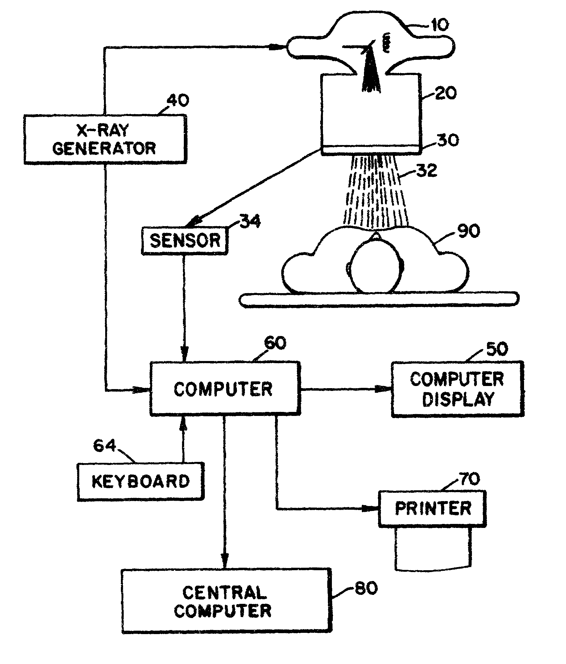
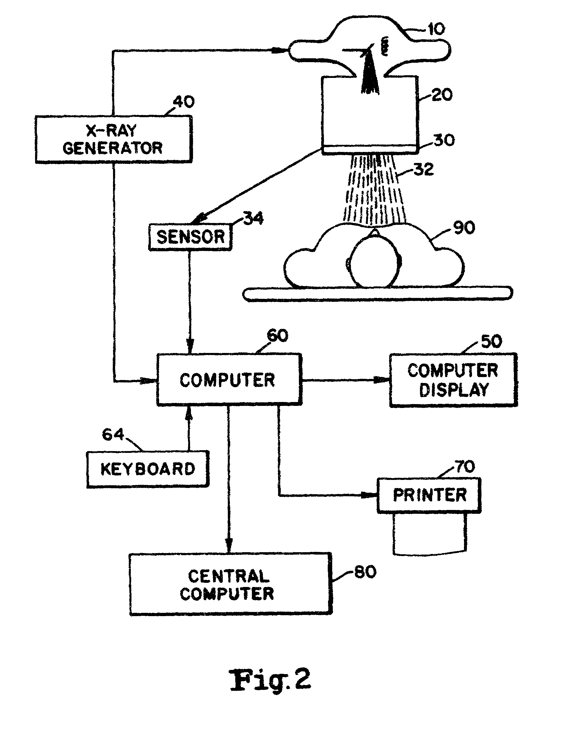
[0048]1. In this first example the technologist will make an examination of the lumbar spine series wherein the patient's movements caused a motion error in one of the pictures. The exposure data recorded for the examination may be as follows:

[0049]The technologist enters into keyboard 64 before the examination starts, the name of the patient and the type of examination (lumbar spine) to be performed. The technologist enters into keyboard 64 the time the examination is started. The technologist positions the patient body part 90 for the first view in the series. The technologist enters in computer 60 the name of the first view which is the AP view. The technologist enters in computer 60 a number which identifies the size of the film to be used. Computer 60 will include the cost of the film size based on the standard information in its ROM. The technologist via keyboard 64 sets each parameter to its correct level for the exposure and takes the x-ray. The technologist ret...

example no.2

EXAMPLE NO. 2

[0054]2. In this example computer 60 may analyze the exposure data of the examination and conclude that the extra exposure in the series was due to the patient breathing during the exposure which is called “a motion error” in Radiology. The technologist enters into keyboard 64 before the examination starts, the name of the patient and the type of examination (lumbar spine) to be performed. The technologist enters into keyboard 64 the time the examination is started. The technologist positions the patient body part 90 for the first view in the series. The technologist enters in computer 60 the name of the first view which is the AP view. The technologist enters in computer 60 a number for the size for the film to be used. Computer 60 will include the cost of the film size based on the standard information in its ROM. The technologist sets each parameter of the input to the x-ray machines to its correct level for the exposure and takes the x-ray. The technologist returns ...

example no.3

EXAMPLE NO. 3

[0056]3. In this example computer 60 may analyze the exposure data of the exam and conclude that the extra exposure was due to the fact that the physician in charge of the matter needed an additional view (or picture) of a particular area to help diagnosis the case. The technologist enters into keyboard 64 before the examination starts, the name of the patient and the type of body part 90 (lumbar spine examination) to be performed. The technologist may manually enter via keyboard the start time of the examination or this may be done electronically by computer 60. The technologist positions the patient body part 90 for the first view in the series. The technologist enters in computer 60 the name of the first view which is the AP view. The technologist enters in computer 60 a number for the size for the film to be used. Computer 60 will include the cost of the film size based on the standard information in its ROM. The technologist sets each parameter to its correct level...


PUM

PropertyMeasurementUnit
angleaaaaaaaaaa
timeaaaaaaaaaa
voltageaaaaaaaaaa

Abstract

The method of creating at least one standard protocol or pattern about the operator, the patient, the examination and/or the machine being used. Monitoring, creating and recording data about at least one of them during the actual performance of the examination. Next, compare this data to a standard protocol to produce certain results or findings about either the revenues and expenses surrounding the exam, the operators performance and skill levels during the exam, the productivity of the machine and operator, etc. Networking the data from more then one machine to a central computer and performing various analyzes, computations and/or calculations on the data from the various machines. The results will provide individual as well as combined totals for all of the machines in a department that download data to the computer.

Description

RELATED CASES[0001]This is a divisional application of my application Ser. No. 09 / 220,064 filed Dec. 23, 1998, now U.S. Pat. No. 6,282,513 entitled A Quality Assurance Method for a Machine and an Operator which is a continuation-in-part application of my prior application Ser. No. 08 / 720,036 filed Sep. 27, 1996, now abandoned entitled Method For Measuring Patient Radiation Dose, which claims the benefit of my provisional application Ser. No. 60 / 004,891 filed Oct. 6, 1995, entitled Patient Dose Monitoring Method.BACKGROUND OF THE INVENTION[0002]The present invention relates to an apparatus and method capable of producing findings which monitor the productivity of an x-ray machine and its operator. The skill and performance of the operator of the x-ray machine during an examination or procedure, is also monitored.[0003]The Radiology department of a hospital may have many machines such as X-ray machines, C.T. scanners, MRI scanners, etc. Also, a Radiology department is similar to a fee...

Claims


Application Information

Patent Timeline
Patent Type & Authority Patents(United States)
IPC IPC(8): G01T1/161G01N33/483G06Q50/00G06Q10/04G16H10/60G16H30/40G16H40/60
CPCG06Q10/04G06Q50/24G06Q50/22G06Q10/10G16H40/60G16H30/40
Inventor STRAWDER, GLENN G.
Owner STRAWDER GLENN G
Why Eureka
Try Eureka