Method for obtaining a tomosynthesis image

a tomosynthesis and image technology, applied in the field of tomosynthesis images, can solve the problems of inability to identify certain calcium deposits and certain cases of opacity, excessive public health costs, limitations of tomosynthesis mammography apparatus, etc., to facilitate the detection of radiological signs, facilitate identification, and improve the effect of examination efficiency

Active Publication Date: 2008-03-06
GENERAL ELECTRIC CO
View PDF9 Cites 17 Cited by
  • Summary
  • Abstract
  • Description
  • Claims
  • Application Information

AI Technical Summary

Benefits of technology

[0018]To this end, the invention proposes projection image acquisition techniques associated with an image processing method used to facilitate the detection of radiology signs in the 3D image. With the acquisition technique and the image processing method, the radiology signs are easier to identify in the tomosynthesis method, thus enabling examination with greater efficiency.
[0019]The invention proposes a novel approach to mammography that advantageously exploits the techniques of digital processing of the radiology image to improve the readability of the information.
[0020]These image-processing methods can be used to cope with a substantial quantity of data in developing novel strategies capable of reducing the time taken to review clinical data and of simplifying access to information of clinical interest.
[0021]The acquisition techniques of the invention can be used to acquire tomosynthesis sequences with an improved strategy for the distribution of the X-ray dose. With the invention, it can be shown that any dose distribution strategy whatsoever that brings about a correction of the prior art strategy leads to improved detection of radiology signs.

Problems solved by technology

However, a mammography machine of this kind produces only a 2D image of the patient's breast which does not provide sufficient information on the presence of a tumor or a calcification and often gives rise to falsely positive interpretations which are both stressful to the patient and entail excessive public health costs.
Furthermore, it happens that certain calcium deposits and certain cases of opacity are not identified.
However, this tomosynthesis mammography apparatus has limitations.
Consequently, the quantity of information to be managed is very great.
Similarly, access to a piece of information of clinical interest takes much more time because this piece of information is sought sequentially in the image volume.
Another problem, which is more specific to mammography but could arise in other fields, is related to the need to be able to analyze microcalcifications which become clinically interesting between 100 μm and 500 μm.
This problem of spatial resolution is critical in tomosynthesis mammography devices.
These devices therefore cannot be used to obtain sufficient image quality for a fine analysis of the microcalcifications.
This volume reconstruction of the entire breast cannot be done with sufficient resolution along the projection axis except by generating a huge volume of data.
This has the consequence of greatly affecting the process of examining the tomography images.
Furthermore, the individual loss of microcalcifications is not the only expected impact since, for clusters of microcalcifications, there is an additional, simultaneous loss of visibility of microcalcifications in the clusters due to reduced depth-of-focus.
This strategy implements a non-uniform distribution of the irradiation dose produced by the X-ray tube during the exposure of the breast.
However, this does not resolve the potential loss of microcalcifications which are due to out-of-plane regions of clinical interest and do not produce an additional volume of data to be combined with the slices.
Furthermore, the workflow may be impaired when the combination of the slices is done at the same time as the display.

Method used


Image

  • Method for obtaining a tomosynthesis image
  • Method for obtaining a tomosynthesis image
  • Method for obtaining a tomosynthesis image

Examples


Embodiment Construction

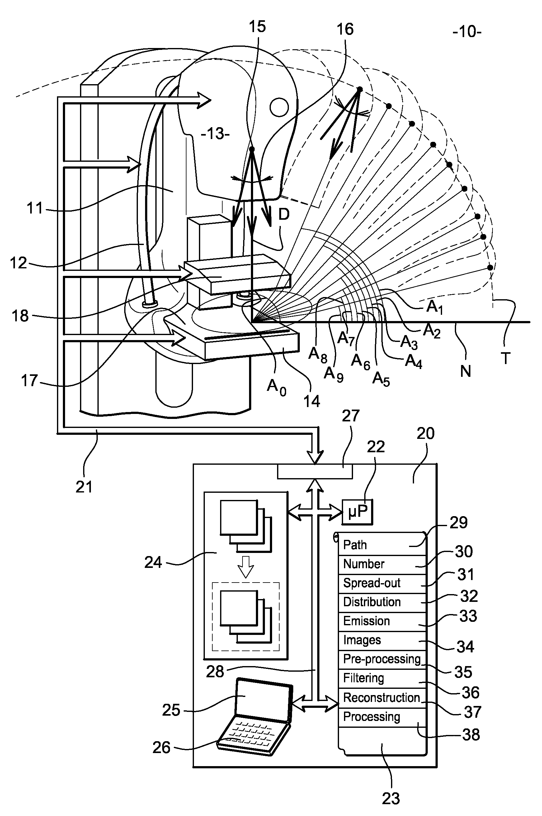
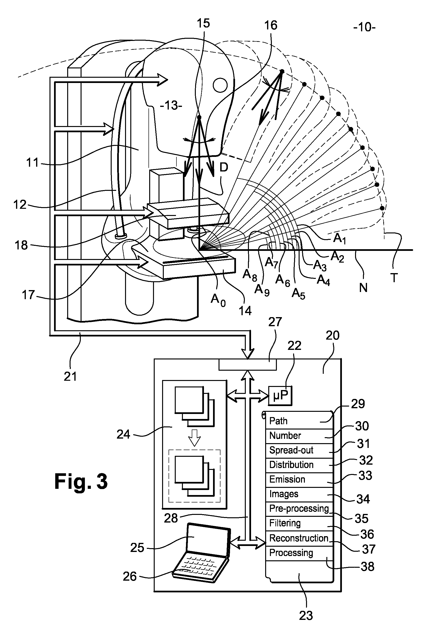
[0071]FIG. 3 shows an X-ray device, especially a mammography machine, according to the invention. This X-ray device 10 has a vertical column 11. On this vertical column 11, there is a hinged arm 12 bearing an X-ray-emitting tube 13 and a detector 14 capable of detecting the X-rays emitted by the tube 13. This arm 12 may be oriented vertically, horizontally or obliquely. The tube 13 is provided with a focus 15 which is the X-ray emitting focus. This focus 15 emits an X-ray beam 16 along a main direction of emission D.

[0072]The arm 12 is hinged on the vertical column 11 in such a way that it can be used to shift the tube 13 along a path T in the form of a circle arc while, at the same time, leaving the detector 14 immobile. Other arrangements are possible, enabling the tube 13 to move in a plane or in a sphere portion. The tube 13 can then take up different positions spread in a tilt between two extreme positions. These two positions are, for example, symmetrical to each other relativ...


PUM


Abstract

In a method for the obtaining a tomosynthesis image for a more selective detection of radiology signs, a dose distribution strategy is proposed. The strategy is defined as a function of a substantially uniform depth-of-focus for a variety of sizes and classes of radiology signs. This strategy is coupled with a digital filtering aimed at ensuring optimum propagation of the signal-to-noise ratio beyond the frequency spectrum. This digital filtering is done by means of a class of adaptive filters required to control the propagation of the noise during the reconstruction. The filter to be applied to each projection of the X-ray tube (4) depends on the dose assigned to this projection.

Description

FIELD OF THE INVENTION[0001]An object of the invention is a method for obtaining a tomosynthesis image for a more selective detection of radiology signs. The present invention can be applied to special advantage but not exclusively in the field of medical imaging and more particularly the field of mammography. The present invention also relates to a medical image reviewing station comprising an image-processing method of this kind.PRIOR ART[0002]Mammography is now widely used for the early detection of lesions associated with breast cancer. The radiology signs to be detected in mammography machines may be either calcium accretions known as microcalcifications which constitute elements more opaque to X-rays than the surrounding tissues or tumors which are expressed in the mammography image by dense zones in which the X-rays are more strongly absorbed then the adjacent zones.[0003]Radiography images are acquired by means of an X-ray mammography apparatus designed to take radiography p...

Claims


Application Information

Patent Timeline
Patent Type & Authority Applications(United States)
IPC IPC(8): A61B6/00
CPCA61B6/025A61B6/482A61B6/544A61B6/542A61B6/502
Inventor SOUCHAY, HENRIFAYE, IBRAHIMAIORDACHE, RAZVAN GABRIEL
Owner GENERAL ELECTRIC CO
Why Eureka
Try Eureka