
Matrix drill bits with back raked cutting elements

a technology of matrix drill bits and cutting elements, which is applied in drill bits, cutting machines, earthwork drilling and mining, etc., can solve the problems of ineffective grinding action of matrix drill bits, cuttings that are often sticky and not thoroughly removed, and the matrix drill bits often experience problems, etc., to achieve the effect of reducing existing problems or eliminating or substantially reducing existing problems

Inactive Publication Date: 2011-05-24
HALLIBURTON ENERGY SERVICES INC
View PDF52 Cites 3 Cited by
  • Summary
  • Abstract
  • Description
  • Claims
  • Application Information

AI Technical Summary

Benefits of technology

This configuration enhances drilling efficiency by effectively cutting through both soft and hard rock formations, reducing material retention and improving bit performance across diverse geological layers.

Problems solved by technology

However, matrix bits often experience problems when drilling in formations that include hard rock formations interspersed with layers or inclusions of soft rock such as soft shale or limestone.
As matrix bits drill through such portions of soft rock the resulting cuttings often have a relatively sticky consistency and are not thoroughly removed by the interaction between the matrix bit and drilling fluid.
Additionally, the grinding action of the matrix bit is often ineffective in relatively soft formations.
As a result, after a matrix bit passes through a layer of soft formation and returns to drilling hard rock, material may remain in the indentations, grooves and cavities of the drill bit, often interfering with the grinding-type action of the drill bit in the hard rock formation.
This material often significantly decreases the overall effectiveness of the drill bit and significantly limits the application of matrix bits.

Method used


Image

  • Matrix drill bits with back raked cutting elements
  • Matrix drill bits with back raked cutting elements
  • Matrix drill bits with back raked cutting elements

Examples


Embodiment Construction

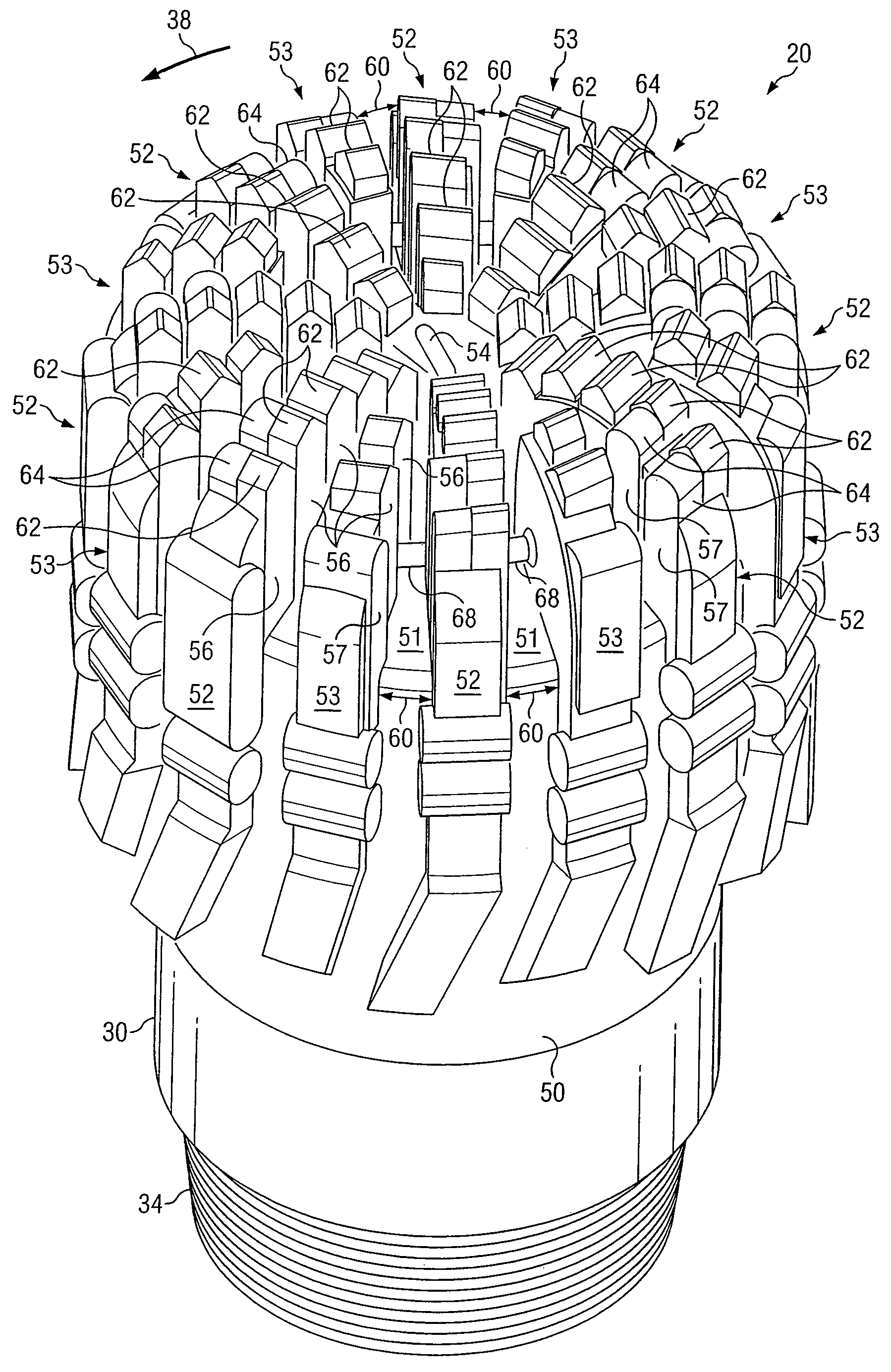
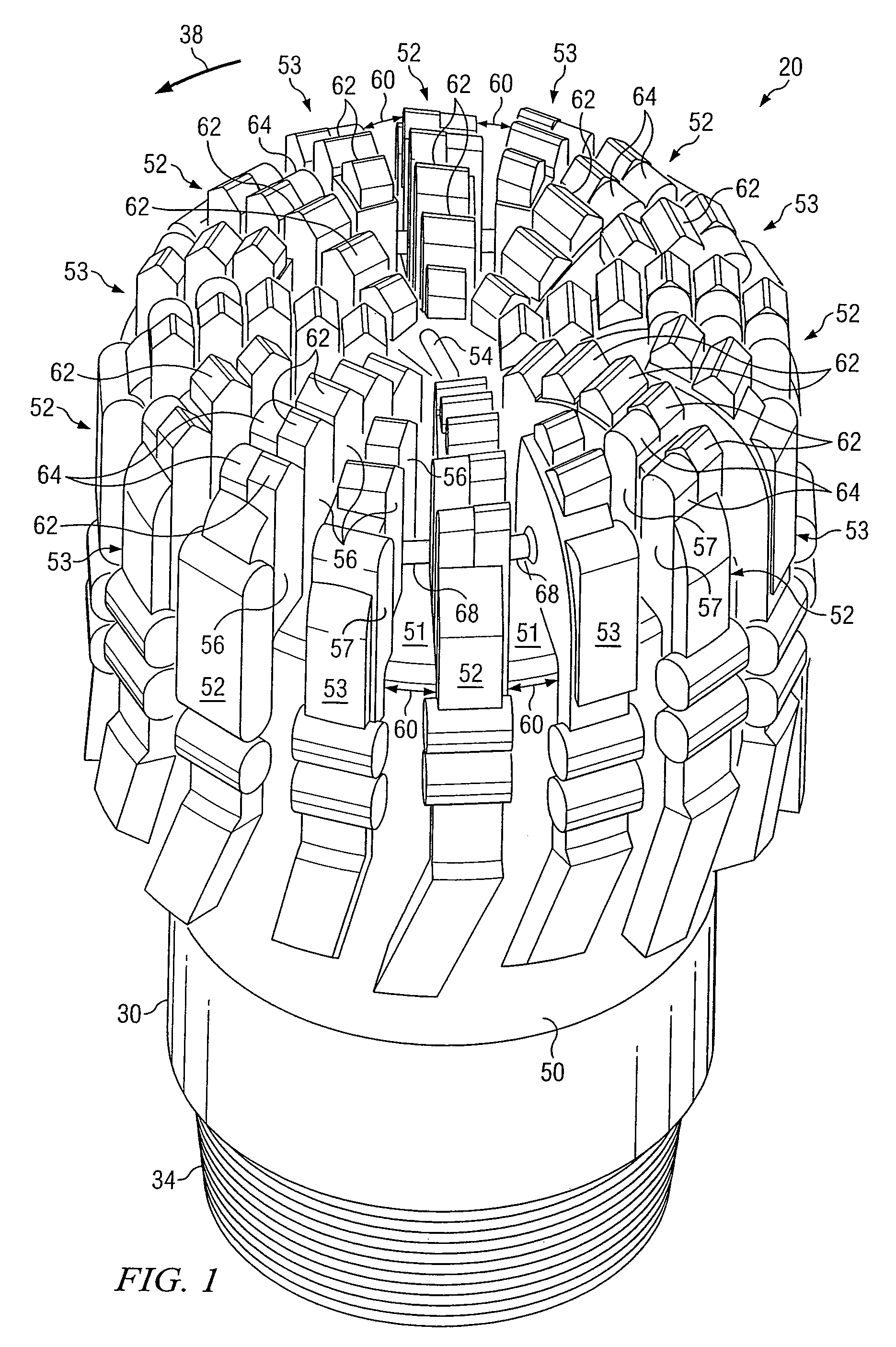
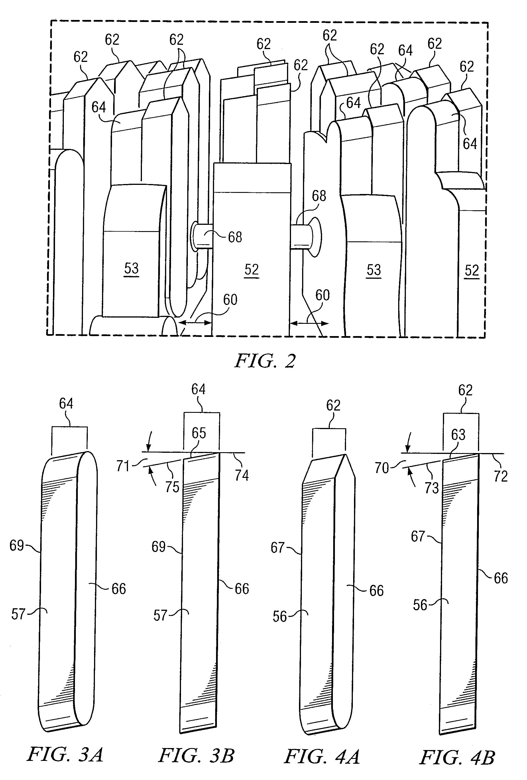
[0016]Preferred embodiments of the disclosure and its advantages are best understood by reference to FIGS. 1-4 wherein like numbers refer to like and corresponding parts.

[0017]The terms “matrix drill bit” and “matrix bit” may be used in this application to refer to any fixed cutter bit formed using matrix material incorporating teachings of the present disclosure. Such drill bits may be used to form well bores or boreholes in subterranean formations. Matrix drill bits incorporating teachings of the present disclosure may include a matrix bit body formed from loose matrix material and combined with a binder alloy in a suitable mold form.

[0018]For some applications the matrix material may include microcrystalline tungsten carbide, cast carbides, cemented carbides, spherical carbides, any other suitable matrix material or a combination thereof. A binder material may be used to infiltrate the matrix material to form a coherent, composite matrix bit body. Binder materials may include, bu...


PUM


Abstract

A matrix drill bit and method of manufacturing a matrix bit having back raked cutting elements is disclosed. In one aspect, a matrix drill bit for well drilling includes a matrix bit body that has a front area in a direction of drilling and two or more diamond impregnated cutting blades protruding from the front area of the matrix bit body. The cutting blades each have a front external surface protruding from the front area of the matrix bit body and present a plurality of back raked downhole interface surfaces in the direction of drilling. The downhole interface surfaces span a leading face and a trailing face where the leading face extends to a first height and the trailing face extends to a second height and the first height is greater than the second height.

Description

RELATED APPLICATION[0001]This application is a continuation of International Patent Application No. PCT / EP2006 / 060834, filed on Mar. 17, 2006.TECHNICAL FIELD[0002]The present invention is related to rotary drill bits and more particularly to matrix drill bits having diamond impregnated back raked cutting structures.BACKGROUND OF THE INVENTION[0003]Rotary drill bits are frequently used to drill oil and gas wells, geothermal wells and water wells. Rotary drill bits may be generally classified as rotary cone or roller cone drill bits and fixed cutter drilling equipment or drag bits. Fixed cutter drill bits or drag bits are often formed with a matrix bit body having cutting elements or inserts disposed at select locations of exterior portions of the matrix bit body. Fluid flow passageways are typically formed in the matrix bit body to allow communication of drilling fluids from associated surface drilling equipment through a drill string or drill pipe attached to the matrix bit body. Su...

Claims


Application Information

Patent Timeline
Patent Type & Authority Patents(United States)
IPC IPC(8): E21B10/54
CPCE21B10/42
Inventor DA SILVA, NUNOSILLEN, VALERIELUYCKX, NICOLAS
Owner HALLIBURTON ENERGY SERVICES INC
Learn More