
Contact of coaxial cable connector

Inactive Publication Date: 2011-05-24
WEALLEYS TECH
View PDF13 Cites 12 Cited by
  • Summary
  • Abstract
  • Description
  • Claims
  • Application Information

AI Technical Summary

Benefits of technology

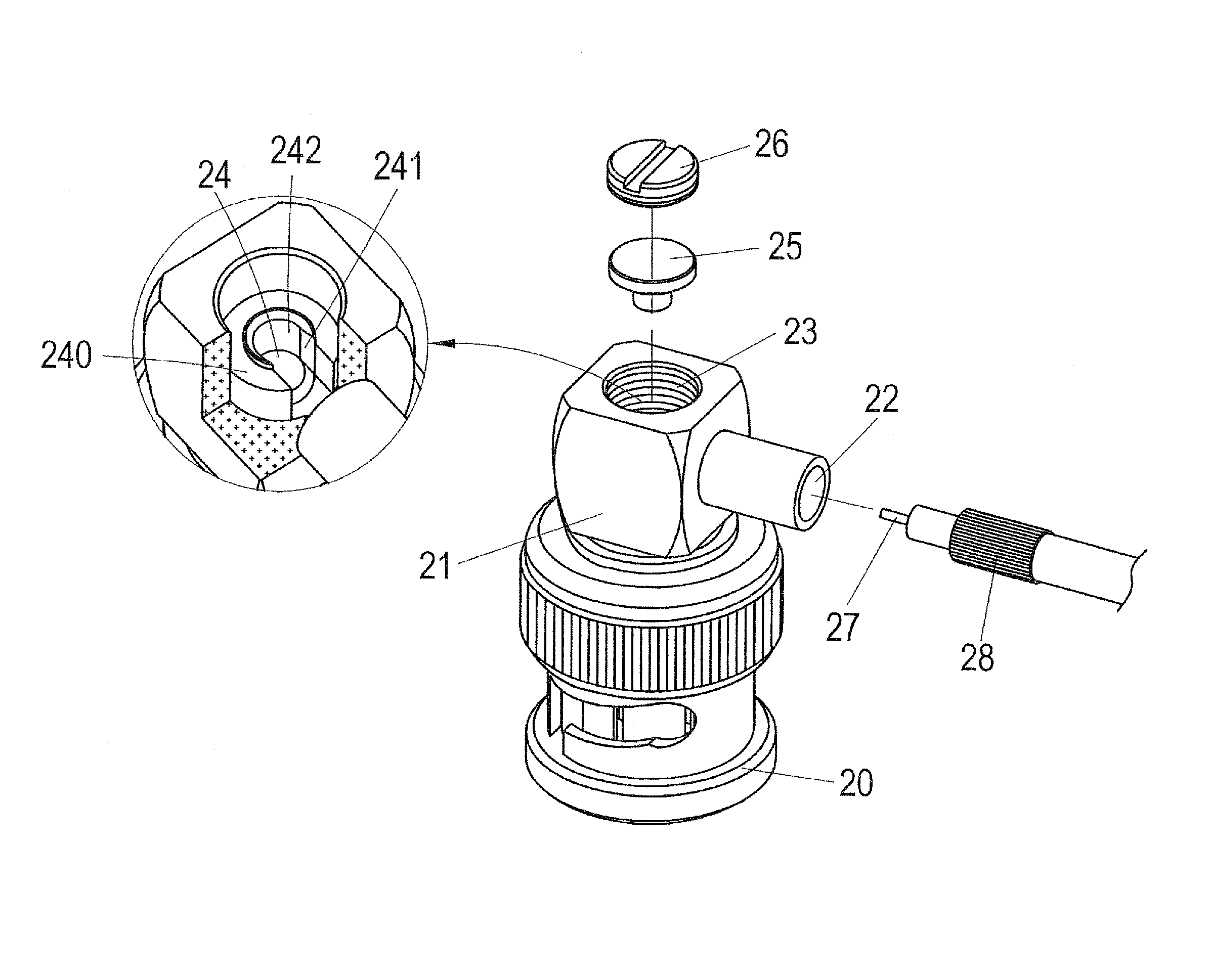
[0010]In order to overcome the above mentioned drawbacks of the conventional coaxial cable connectors, the present invention aims to provide a coaxial cable connector that comprises a connector body, a contact chamber, a copper sleeve, and an observation window opening. A central contact bore is formed inside the observation window opening and an insulation layer is set between the central contact bore and the contact chamber. The central contact bore has a notch formed in a side thereof close to the copper sleeve to receive a core conductor of the coaxial cable to insert therein. The central contact bore also has a stop wall that prevents the core conductor from extending beyond the central contact bore. An insulation block covers the central contact bore, and a window opening bolt is set in engagement with and thus closes the observation window opening to force a projection of the insulation block to depress the core conductor to engage the central contact bore for electrical contact therebetween. The copper sleeve is then processed to secure an outer conductor of the coaxial cable therein. As such, assembling the coaxial cable in a depression manner effectively reduces product flaw rate and shortens the working hour.

Problems solved by technology

In such an arrangement, the window opening bolt 16 can be partly exposed to get into contact with the contact chamber 1 and thus leading to shorting.
Further, the observation window opening 13 provides only a very limited space, which makes the operation difficult.
Apparently, the conventional coaxial cable connector has disadvantages as follows:
(1) The assembling requires soldering, which is time consuming.
(2) Soldering operation often leads to shorting and electrical abnormality.
(4) The observation window opening of the conventional connector is small and a soldering iron that is used to perform soldering operation is relatively large; this makes the operation difficult and leads to high product flaw rate.
(5) Repairing of a flaw product is generally impossible and this makes the manufacturing costs very high.

Method used


Image

  • Contact of coaxial cable connector
  • Contact of coaxial cable connector
  • Contact of coaxial cable connector

Examples


Embodiment Construction

[0022]The following descriptions are exemplary embodiments only, and are not intended to limit the scope, applicability or configuration of the invention in any way. Rather, the following description provides a convenient illustration for implementing exemplary embodiments of the invention. Various changes to the described embodiments may be made in the function and arrangement of the elements described without departing from the scope of the invention as set forth in the appended claims.

[0023]Referring to FIGS. 2 and 3, which show an exploded view and a perspective view of a coaxial cable connector according to the present invention, as well as a coaxial cable jointed to the coaxial cable connector, as shown in the drawings, the coaxial cable connector of the present invention, which can be a right-angled connector, comprises a connector body 20, a contact chamber 21, a copper sleeve 22, and an observation window opening 23. Structurally, the connector body 20 forms therein the con...


PUM


Abstract

A coaxial cable connector includes a connector body, a contact chamber, a copper sleeve, and an observation window opening. A central contact bore is formed inside the observation window opening and an insulation layer is set between the central contact bore and the contact chamber. The central contact bore has a notch formed in a side thereof close to the copper sleeve to receive a core conductor of the coaxial cable to insert therein. The central contact bore also has a stop wall that prevents the core conductor from extending beyond the central contact bore. An insulation block covers the central contact bore, and a window opening bolt is set in engagement with and thus closes the observation window opening to force a projection of the insulation block to depress the core conductor to engage the central contact bore for electrical contact therebetween.

Description

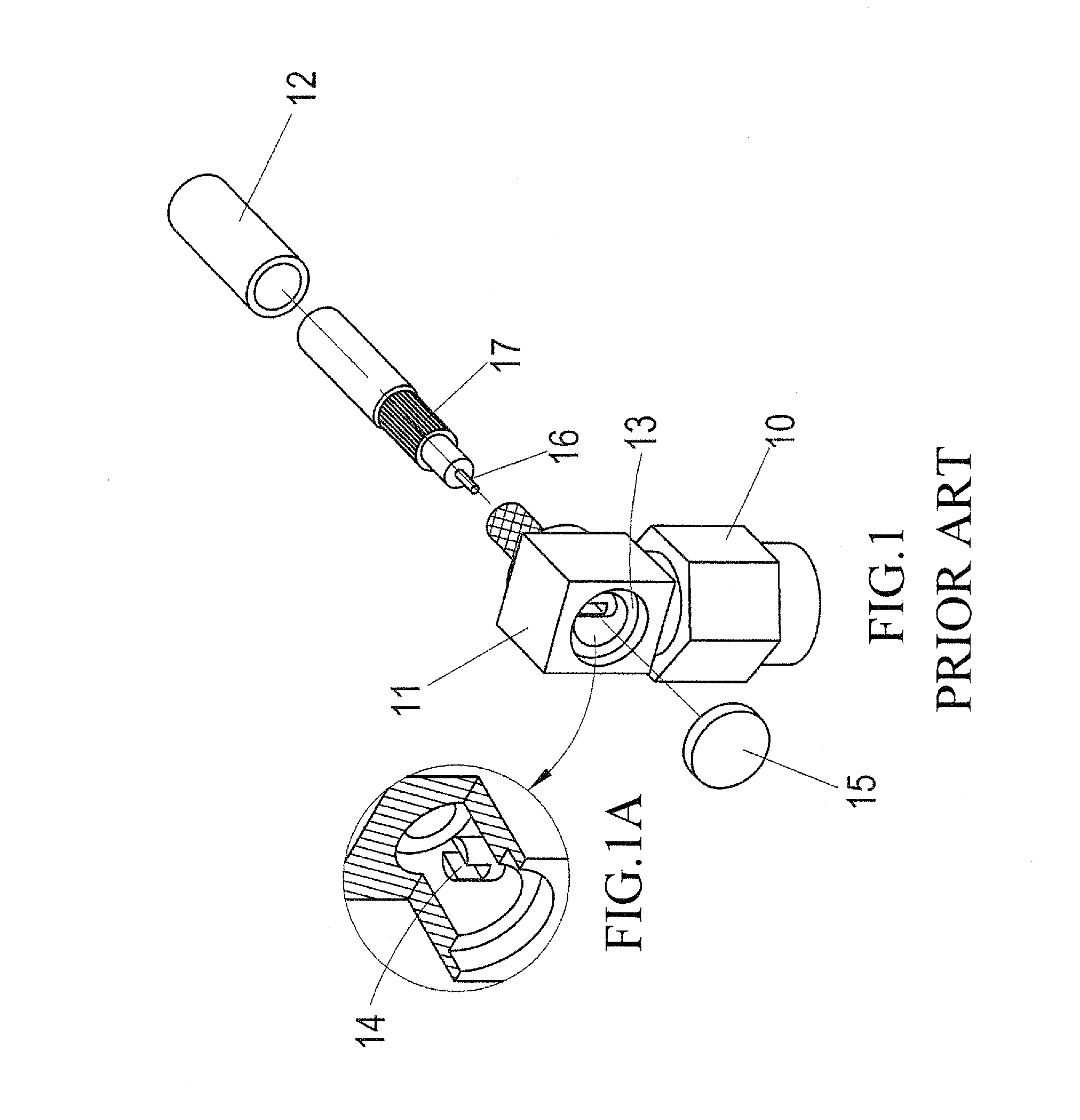
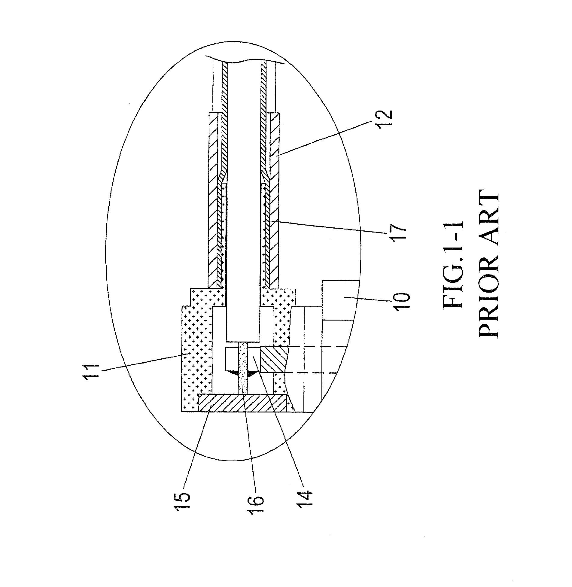
(a) TECHNICAL FIELD OF THE INVENTION[0001]The present invention generally relates to a contact of a coaxial cable connector, and more particularly to a depressed contact of a coaxial cable connector.(b) DESCRIPTION OF THE PRIOR ART[0002]Referring to FIGS. 1 and 1-1, which are respectively an exploded view and a cross-sectional view of a conventional coaxial cable connector, together with a coaxial cable, the conventional coaxial cable connector comprises a connector body 10, a contact chamber 11, a copper sleeve 12, an observation window opening 13, a central contact bore 14 (see FIG. 1A), and a window opening cover 15, and the coaxial cable has an core conductor 16 and an outer conductor 17. Assembling is conducted as follows. The core conductor 16 is inserted into the central contact bore 14 and is fixed thereto by soldering. The outer conductor 17 is then riveted to the copper sleeve 12. The window opening cover 15 then closes the observation window opening 13. In such an arrange...

Claims


Application Information

Patent Timeline
IPC IPC(8): H01R4/24
CPCH01R9/05H01R4/36
Inventor LIU, LI-CHEN
Owner WEALLEYS TECH
Learn More