Solid electrolytic capacitor and method of manufacturing the same

a solid electrolytic capacitor and solid electrolytic technology, which is applied in the manufacture of electrolytic capacitors, capacitors, electrical apparatus casings/cabinets/drawers, etc., can solve the problems of increasing the thermal stress applied to solid electrolytic capacitors, increasing the leaking current, so as to reduce the density of the separator and improve the effect of solid electrolytic capacitors

Inactive Publication Date: 2011-05-24
NICHICON CORP
View PDF13 Cites 7 Cited by
  • Summary
  • Abstract
  • Description
  • Claims
  • Application Information

AI Technical Summary

Benefits of technology

[0009]The present invention has been made in view of the above circumstances, and provides a method of manufacturing a solid electrolytic capacitor in which breaking of a separator during rolling is restrained and swelling caused by a reflow heat is restrained. And the present invention provides a solid electrolytic capacitor in which swelling caused by reflow heat is restrained.
[0011]With the method, the separator has a given strength, because the separator includes the natural fiber during the rolling of the anode foil and the cathode foil. Therefore, breaking of the separator may be restrained during the rolling. Density of the separator is reduced after the natural fiber is removed from the separator. Filling density of the electrolytic layer is increased between the anode foil and the cathode foil. And the electrolytic layer is stabilized. Consequently, ESR of the solid electrolytic capacitor may be reduced. And a reaction between oxidizer and the natural fiber may be restrained during a heating process. Therefore, swelling may be restrained.
[0013]With the structure, filling density of the electrolytic layer is increased because density of the separator is reduced. Therefore, ESR of the solid electrolytic capacitor may be improved.

Problems solved by technology

This may result in increase of thermal stress applied to a solid electrolytic capacitor, swelling of the capacitor, and degradation of the capacitor.
This results in increase of leaking current.
This results in increase of the leaking current.
This results in a barrier during soldering.
A separator made of only vinylon fiber is expensive and has a high density.
It is difficult to provide an inexpensive capacitor having high ESR, with the art disclosed in Document 4.
However, the anode oxide coating may be degraded because of thermal stress, and the leaking current may be increased.
However, the synthesized fiber separator is not generally used and is expensive.
It is therefore difficult to provide an inexpensive capacitor.
And it is difficult to reduce the density of the synthesized separator compared to a natural fiber separator.
When a rolled element is fabricated with a low density separator manufacturable with present technology, strength of the separator may not be sufficient.
In this case, the separator may be broken during rolling.

Method used


Image

  • Solid electrolytic capacitor and method of manufacturing the same
  • Solid electrolytic capacitor and method of manufacturing the same
  • Solid electrolytic capacitor and method of manufacturing the same

Examples


first embodiment

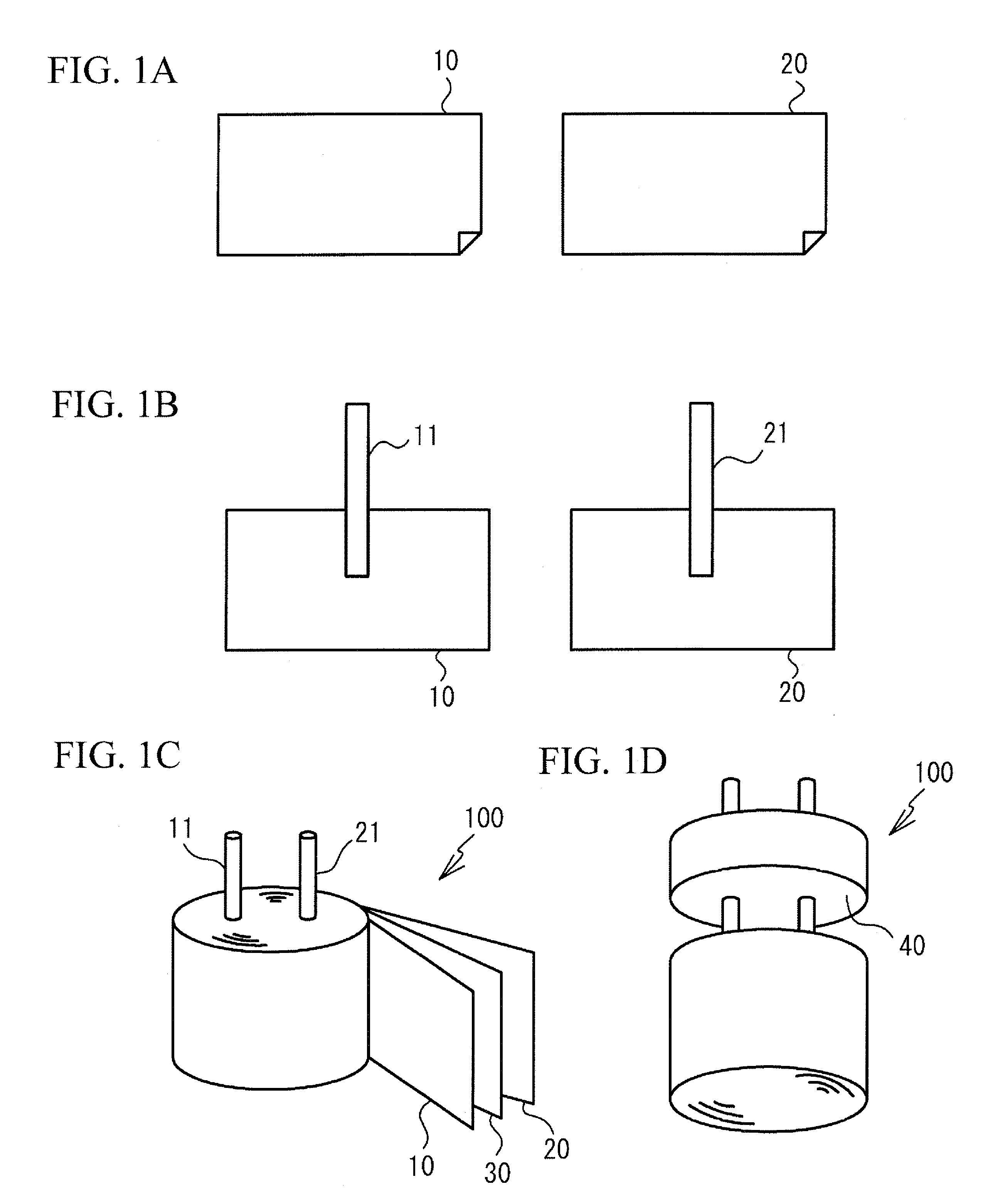
[0020]FIG. 1A through 3B illustrate a method of manufacturing a solid electrolytic capacitor in accordance with a first embodiment. As shown in FIG. 1A, an anode foil 10 and a cathode foil 20 are provided. The anode foil 10 is made of a valve metal having a dielectric oxide coating (not illustrated) formed on a surface thereof. The valve metal used for the anode foil 10 is a metal such as aluminum. The dielectric coating may be formed when a surface of the valve metal is subjected to an etching treatment and a chemical oxidizing treatment. The cathode foil 20 is made of a metal foil such as aluminum holding carbide grain (not illustrated) on a surface thereof. The anode foil 10 and the cathode foil 20 are substantially isometric to each other.

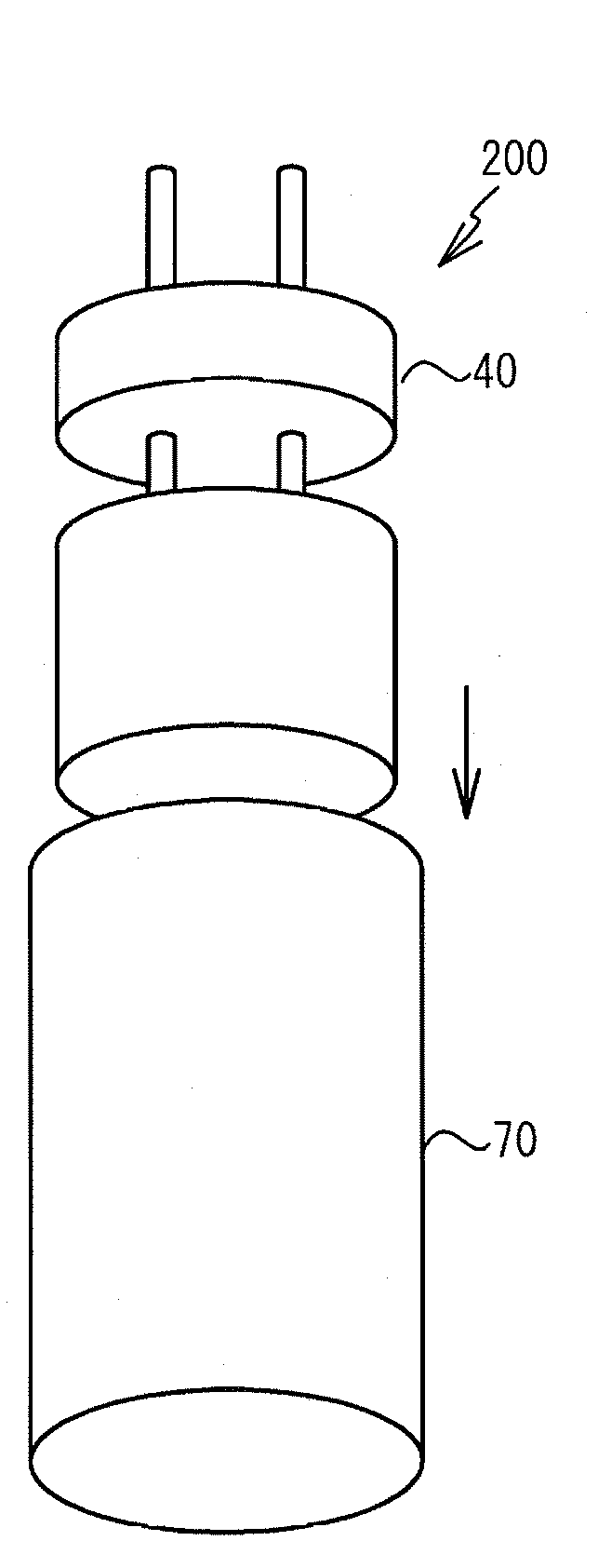
[0021]Next, as shown in FIG. 1B, an anode terminal 11 is jointed to the anode foil 10. A cathode terminal 21 is jointed to the cathode foil 20. Then, as shown in FIG. 1C, the anode foil 10, the cathode foil 20 and a separator 30 are rolled toge...

examples

[0040]The solid electrolytic capacitor 300 and the solid electrolytic capacitor 300a were fabricated.

first example

[0041]The solid electrolytic capacitor 300 shown in FIG. 4A was fabricated in a first example. The anode foil 10 was formed of an aluminum foil that was subjected to an etching treatment and a chemical conversion treatment and had a width of 2.7 mm. The cathode foil 20 was formed of an aluminum that had a width of 2.7 mm and held the carbon grains on the surface of the cathode foil 20. The anode foil 10, the cathode foil 20 and the separator 30 were rolled together, the separator 30 being between the anode foil 10 and the cathode foil 20.

[0042]The separator 30 is a mixed fiber in which hemp fiber and polyamide resin are mixed in a weight ratio of 1:1. Cellulose-degrading enzyme made by Amano Enzyme Inc. was used as the enzyme for degrading the natural fiber. The enzyme was solved in pure water. And water solution having 1.0 weight % was formed. The rolled element 100 had been immersed in the water solution for 12 hours in a temperature-controlled bath having temperature of 50 degree...


PUM

PropertyMeasurementUnit
densityaaaaaaaaaa
weight ratioaaaaaaaaaa
densityaaaaaaaaaa

Abstract

A method of manufacturing a solid electrolytic capacitor includes: rolling an anode foil, a cathode foil and a separator together, the separator being a mixed fiber composed of a chemical fiber and a natural fiber and being between the anode foil and the cathode foil; degrading and removing the natural fiber with enzyme; and forming an electrolytic layer composed of solid polymer between the anode foil and the cathode foil after degrading and removing the natural fiber.

Description

BACKGROUND OF THE INVENTION[0001]1. Field of the Invention[0002]The present invention relates to a solid electrolytic capacitor and a method of manufacturing the solid electrolytic capacitor.[0003]2. Description of the Related Art[0004]Recently, a solder including no lead is being used in a reflow process in consideration of environmental problem. The solder has a melting point higher than that of a solder including lead. It is therefore necessary to increase temperature of the reflow compared to that of conventional reflow. This may result in increase of thermal stress applied to a solid electrolytic capacitor, swelling of the capacitor, and degradation of the capacitor.[0005]Japanese Patent Application Publication No. 11-204377 (hereinafter referred to as Document 1) discloses an art where a polymerized element is protected by a thermoset resin, in order to restrain the swelling. Japanese Patent Application Publication No. 2000-58389 (hereinafter referred to as Document 2) disclos...

Claims


Application Information

Patent Timeline
Patent Type & Authority Patents(United States)
IPC IPC(8): H01G9/00H01G9/02H01G9/028
CPCH01G9/0036H01G9/151H01G9/02Y10T29/435H01G13/00H01G9/08
Inventor FUNAHASHI, MINORUUEDA, AKIRAYAMADA, KATSUHARU
Owner NICHICON CORP
Why Eureka
Try Eureka