Plenoptic camera with large depth of field

Active Publication Date: 2011-05-24
ADOBE INC
View PDF41 Cites 149 Cited by
  • Summary
  • Abstract
  • Description
  • Claims
  • Application Information

AI Technical Summary

Benefits of technology

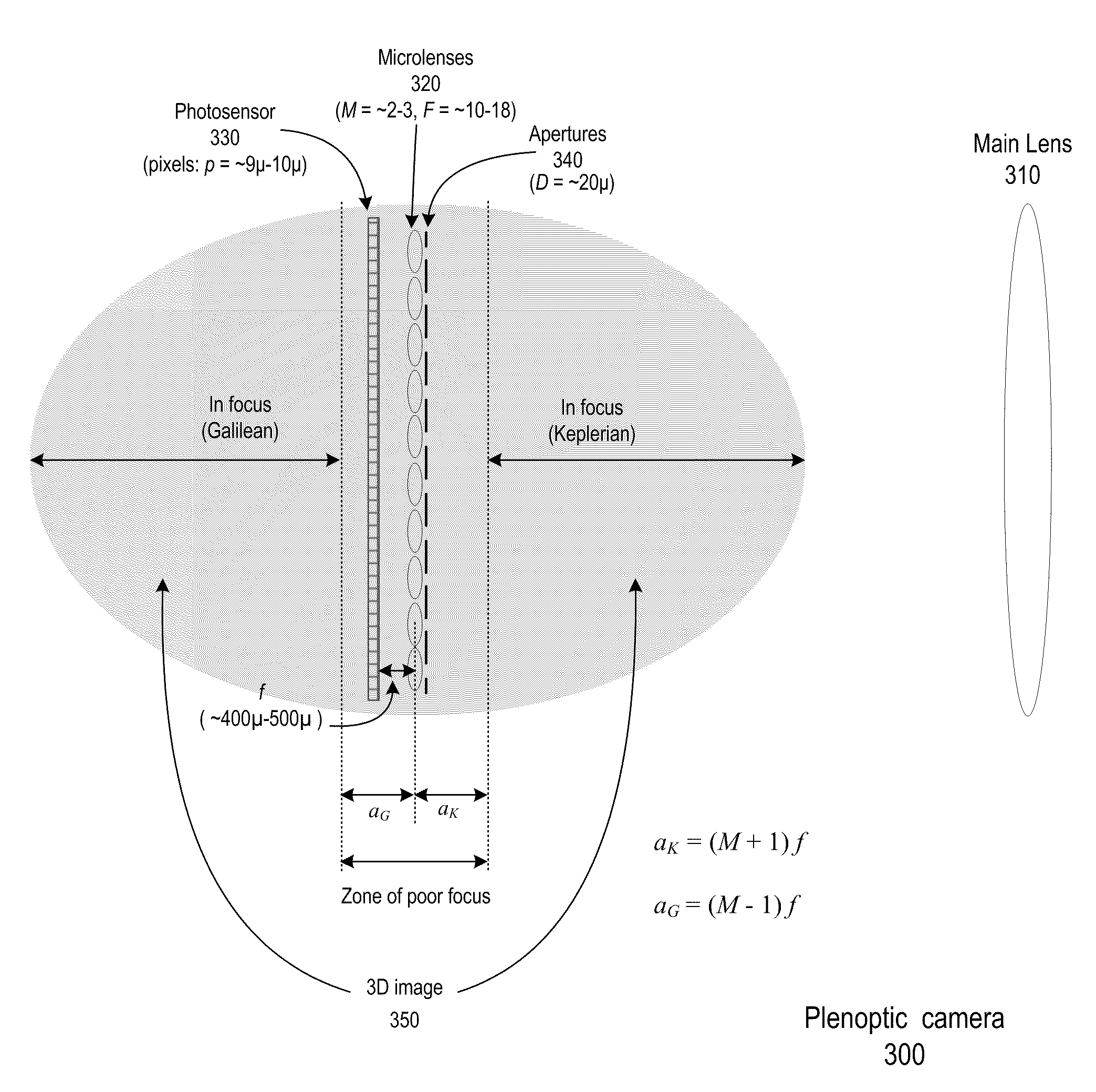
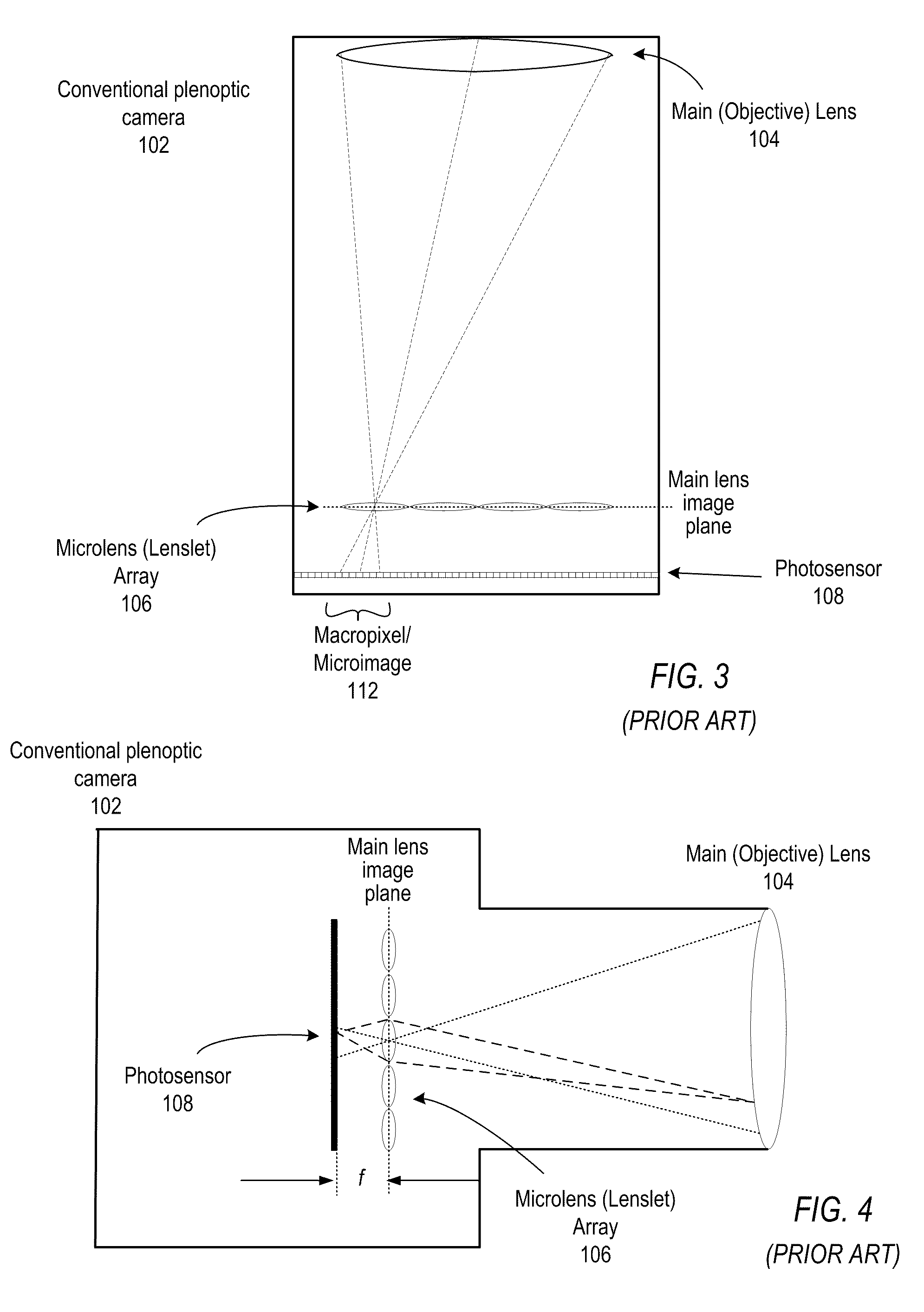
[0013]Various embodiments of plenoptic cameras with large depth of field are described. Depending on whether the main lens image is in front or behind the microlenses, a plenoptic camera works respectively as an array of Keplerian telescopes (Keplerian telescopic case) or Galilean telescopes (Galilean telescopic case). However, conventional plenoptic camera designs tend to have a limited depth of field. For example, in a conventional plenoptic camera using inverse magnification M=14 and F=4, within about 7 mm of the microlens array there is a zone of poor focus. Because of this limited depth of field, it is impractical for conventional plenoptic cameras to realize both Keplerian telescopic and Galilean telescopic imaging at the same time (that is, to capture a single image of a scene using both modes), since a large region of the scene would be out-of-focus.
[0014]A design methodology is described in which the relationships among various plenoptic camera parameters, including inverse magnification, F-number, focal length, wavelength, and pixel size, may be analyzed to design plenoptic cameras that provide increased depth-of-field when compared to conventional plenoptic cameras. Using this design methodology, it is possible to design plenoptic cameras with increased depth of field, and with which both Keplerian telescopic and Galilean telescopic imaging can be realized at the same time.
[0015]Embodiments of a plenoptic camera are described, which may be implemented according to the design methodology, and in which both Keplerian telescopic and Galilean telescopic imaging can be realized at the same time while providing a larger depth of field than is realized in conventional plenoptic cameras, thus capturing light-field images that capture “both sides” in which all but a small region of the scene is in focus. In some embodiments, apertures may be added to the microlenses so that depth of field is increased. In an example embodiment, the

Problems solved by technology

However, this 2-D image contains no information about the direction of the light that strikes the photosensor.
Thus, conventional cameras fail to capture a large amount of optical information.
Not only is this a disappointingly modest resolution (any cell phone today will have better resolution), any particular rendered view only uses one out of every 3,720 pixels from the flat imagery.
The large disparity between the resolution of the flat and the rendered images is extraordinarily wasteful for photographers who are ultimately interested in taking photographs rather than capturing flat representations of the radiance.
However, conventional plenoptic camera designs, as illustrated in FIGS. 3 and 4, tend to have a limited depth of field.
Furthermore, because of this limited depth of field, it is impractical for conventional pleno

Method used


Image

  • Plenoptic camera with large depth of field
  • Plenoptic camera with large depth of field
  • Plenoptic camera with large depth of field

Examples


example results

[0096]FIGS. 13 through 16 show example images or portions of images captured with an embodiment of the plenoptic camera as described above. FIG. 13 shows a crossed eye stereo view. Two stereo views of a captured scene may be generated, as illustrated in FIG. 13. The plenoptic camera is synthetically focused on the “Fluid Dynamics” book. The stereo views may be synthetically generated (and synthetically focused) from the main image inside the plenoptic camera, observed through the microlens array. In this particular case, the “Optical System” book is mapped behind the microlenses as a virtual image, and is observed in Galilean mode. In FIG. 13, the sharp imaging of the plenoptic camera system due to the large depth of field may be observed.

[0097]In capturing the example images of FIGS. 13 through 16, the plenoptic camera was physically focused exactly on the text at the top of the “EG” book. This means that the main image of this area falls in the zone of poor focus within 1.5-2 mm f...


PUM


Abstract

Methods and apparatus for light-field capture with large depth of field. A design methodology is described in which the relationships among various plenoptic camera parameters, including inverse magnification, F-number, focal length, wavelength, and pixel size, may be analyzed to design plenoptic cameras that provide increased depth-of-field when compared to conventional plenoptic cameras. Plenoptic cameras are described, which may be implemented according to the design methodology, and in which both Keplerian telescopic and Galilean telescopic imaging can be realized at the same time while providing a larger depth of field than is realized in conventional plenoptic cameras, thus capturing light-field images that capture “both sides” in which all but a small region of the scene is in focus. In some embodiments, apertures may be added to the microlenses so that depth of field is increased.

Description

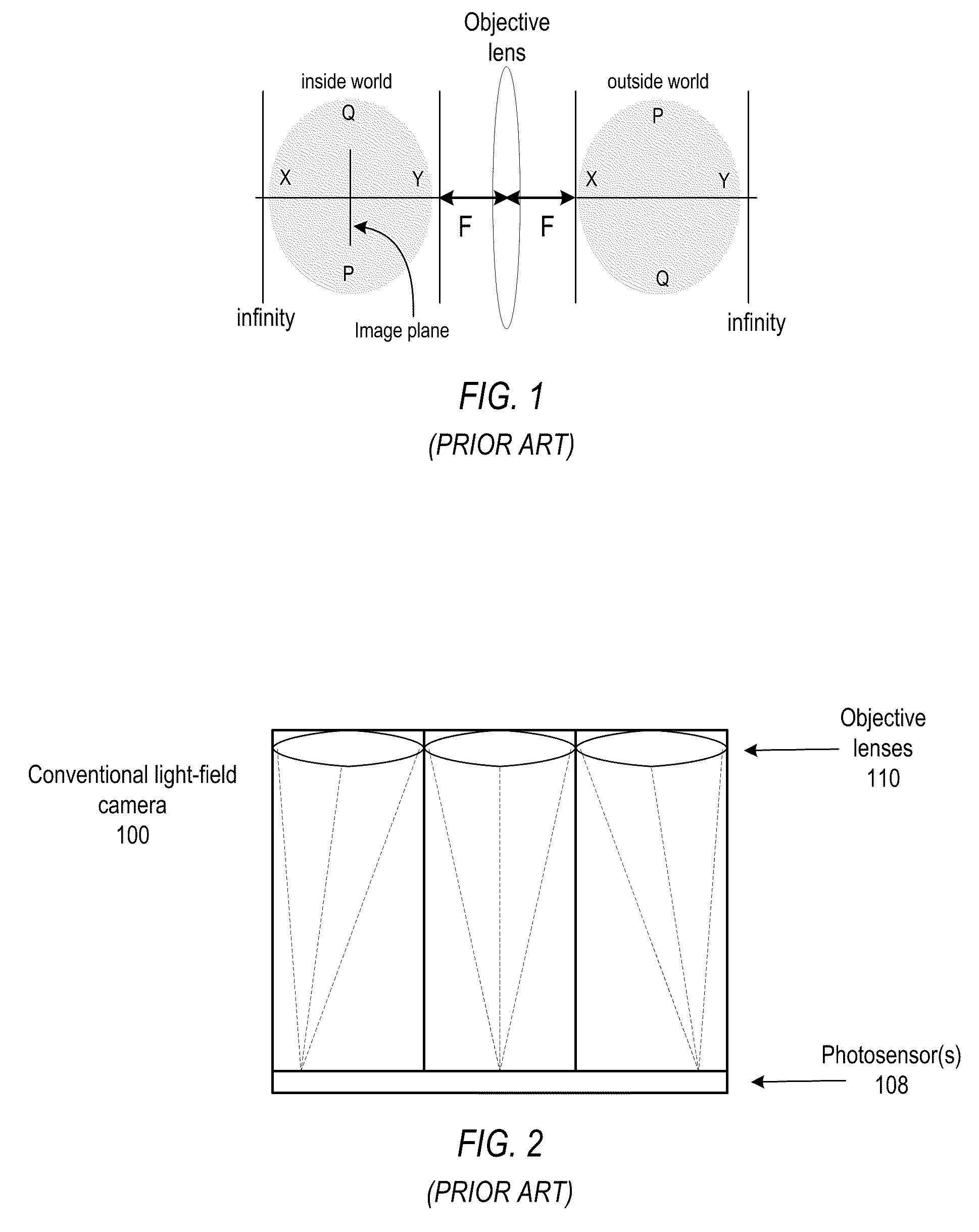
PRIORITY INFORMATION[0001]This application claims benefit of priority of U.S. Provisional Application Ser. No. 61 / 121,846 entitled “Methods and Apparatus for Focusing and Depth of Field in Radiance Cameras” filed Dec. 11, 2008, the content of which is incorporated by reference herein in its entirety.BACKGROUNDDescription of Related Art[0002]In a conventional camera, the main lens maps the 3D world of the scene outside camera into a 3D world inside camera. FIG. 1 illustrates imaging in a conventional camera. “Inside world” represents inside the camera. The shaded oval regions represent the order of depths in the outside world, and the corresponding depths inside the camera. One particular image plane inside the camera is shown. The mapping of the 3D world of the scene outside camera into a 3D world inside camera is governed by the lens equation:[0003]1A+1B=1Fwhere A and B are respectively the distances from the lens to the object plane and from the lens to the image plane. This equat...

Claims


Application Information

Patent Timeline
IPC IPC(8): G03B41/00
CPCH04N13/0228H04N5/2258H04N13/229H04N23/45
Inventor GEORGIEV, TODOR G.
Owner ADOBE INC
Why Eureka
Try Eureka