Linear roller bearing element

a technology of roller bearings and elements, applied in the direction of sliding contact bearings, linear bearings, bearings, etc., can solve the problem of little installation space and achieve the effect of reducing nois

Active Publication Date: 2011-05-31
AMK ARNOLD MUELLER GMBH & CO KG
View PDF11 Cites 9 Cited by
  • Summary
  • Abstract
  • Description
  • Claims
  • Application Information

AI Technical Summary

Benefits of technology

[0006]Accordingly, it is an object of the present invention to create a linear roller bearing element of the type described in the preamble, which enables the rolling elements to circulate smoothly without being subjected to greater loads, with a minimum of noise, using simple means.
[0008]As a result, individual, independent and ready-to-install raceway elements are created, with which the individual raceways remain in a fixed, permanent relation to each other. The raceway elements include the carrier raceway, return, and turnaround, including the rolling elements. Due to this fixed, permanent relationship, there is no risk that, e.g., the return channels may become displaced relative to the carrier raceways of the carrier body.
[0009]The roller bearing element operates quietly, with low wear and the associated long service life, is small and compact, and requires very little installation space when installed in a linear roller bearing guide. In this state, due to the single-axis or biaxial, convex or concave curvature on the back side of the carrier body, the roller bearing element enables the carrier body to automatically adapt to the course of the raceways of the guide rail, and to distribute the load on the individual rolling elements as evenly as possible. As a result, essentially the same load is applied in each row, in every load state.
[0010]Furthermore, since the particular return channels are located on the side, the carrier body may be designed small and compact in terms of its cross-sectional expansion, since its support cross section need not be reduced by return channels that would extend in the region of the carrier body. The same applies for the support region of the guide carriage, on which the carrier body rests. This support cross section does not need to be reduced in size and therefore weakened, either, as a result of the location of the return channels. It is advantageous that the support of the raceway elements therefore takes place via the back of the carrier body in a solid region of the guide carriage. The stiffness of a roller bearing guide is increased as a result. The manufacturing costs are also reduced. It is also advantageous that the raceway elements are acted upon with a spring force acting in the direction of the guide rail. As a result, even when play should arise on one side when force is applied, therefore resulting in displacement, the particular raceway element is still pressed with the rolling elements against the guide rail thereby ensuring constant contact between the rolling elements and the related guide surfaces and preventing flat spots from forming on the rolling elements.
[0011]This is advantageous with highly dynamic drives in particular, since all load bearing rolling elements are accelerated by the contact with the guide raceways. This results in a roller bearing circulation without slip. This makes it possible to design the raceways for the rolling elements as a four-point contact bearing with a small contact angle. In this manner, the load-bearing capacity of the rolling element contact may be nearly doubled. This results in linear roller bearing guides with extremely high load-bearing capacities.

Problems solved by technology

The roller bearing element operates quietly, with low wear and the associated long service life, is small and compact, and requires very little installation space when installed in a linear roller bearing guide.

Method used


Image

  • Linear roller bearing element
  • Linear roller bearing element
  • Linear roller bearing element

Examples


Embodiment Construction

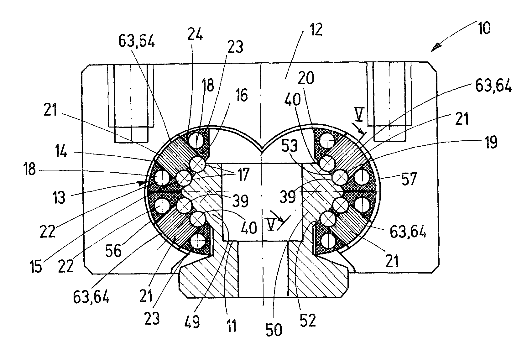
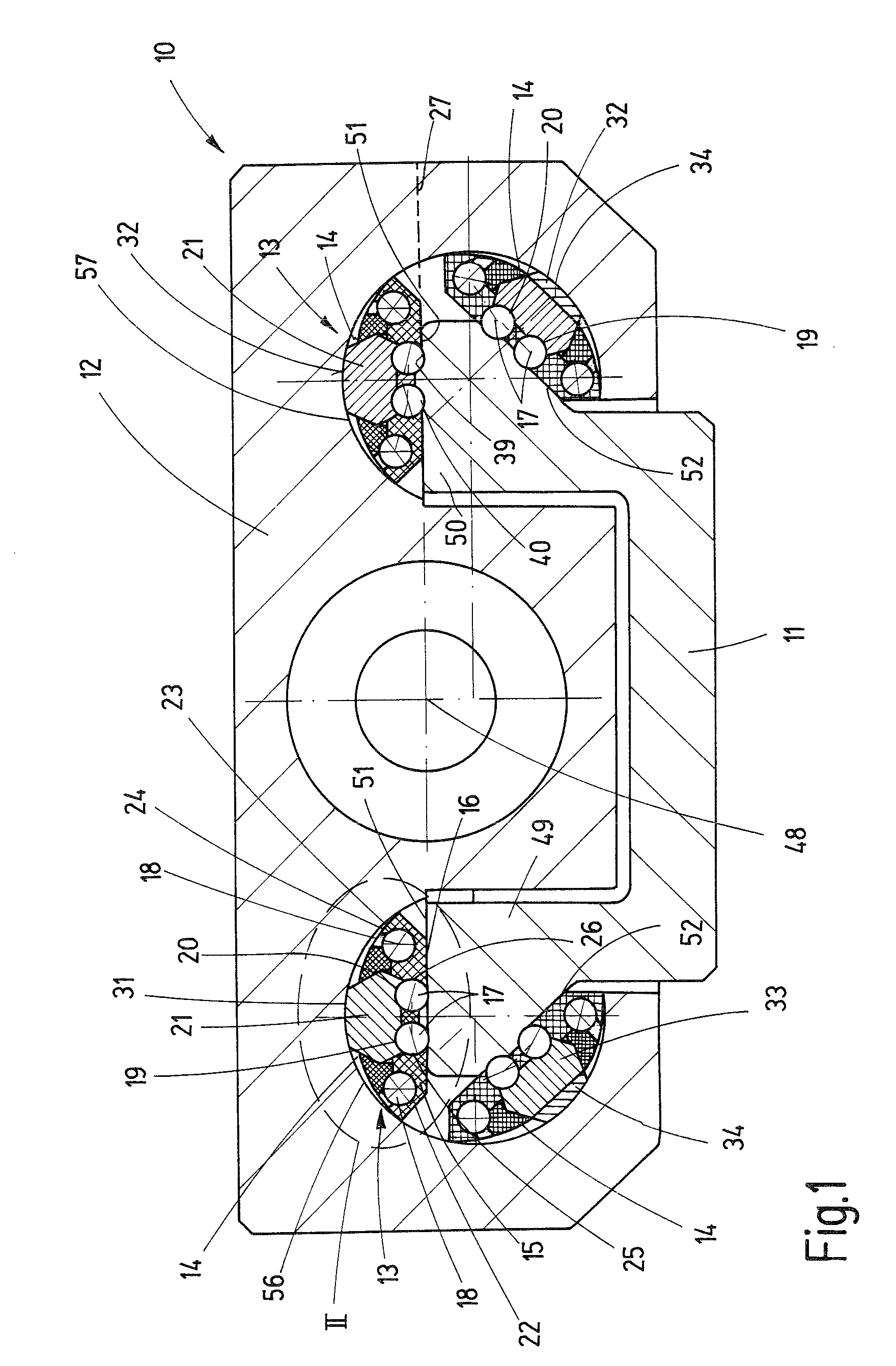
[0023]FIGS. 1 and 2 are schematic depictions of a linear roller bearing guide 10 with a guide carriage 12 or the like supported on a guide rail 11 such that it is displaceable relative thereto; at least one linear roller bearing element 13—in the form of an independent, ready-to-install raceway element 14—is located between guide rail 11 and guide carriage 12, in order to guide the guide carriage 12.

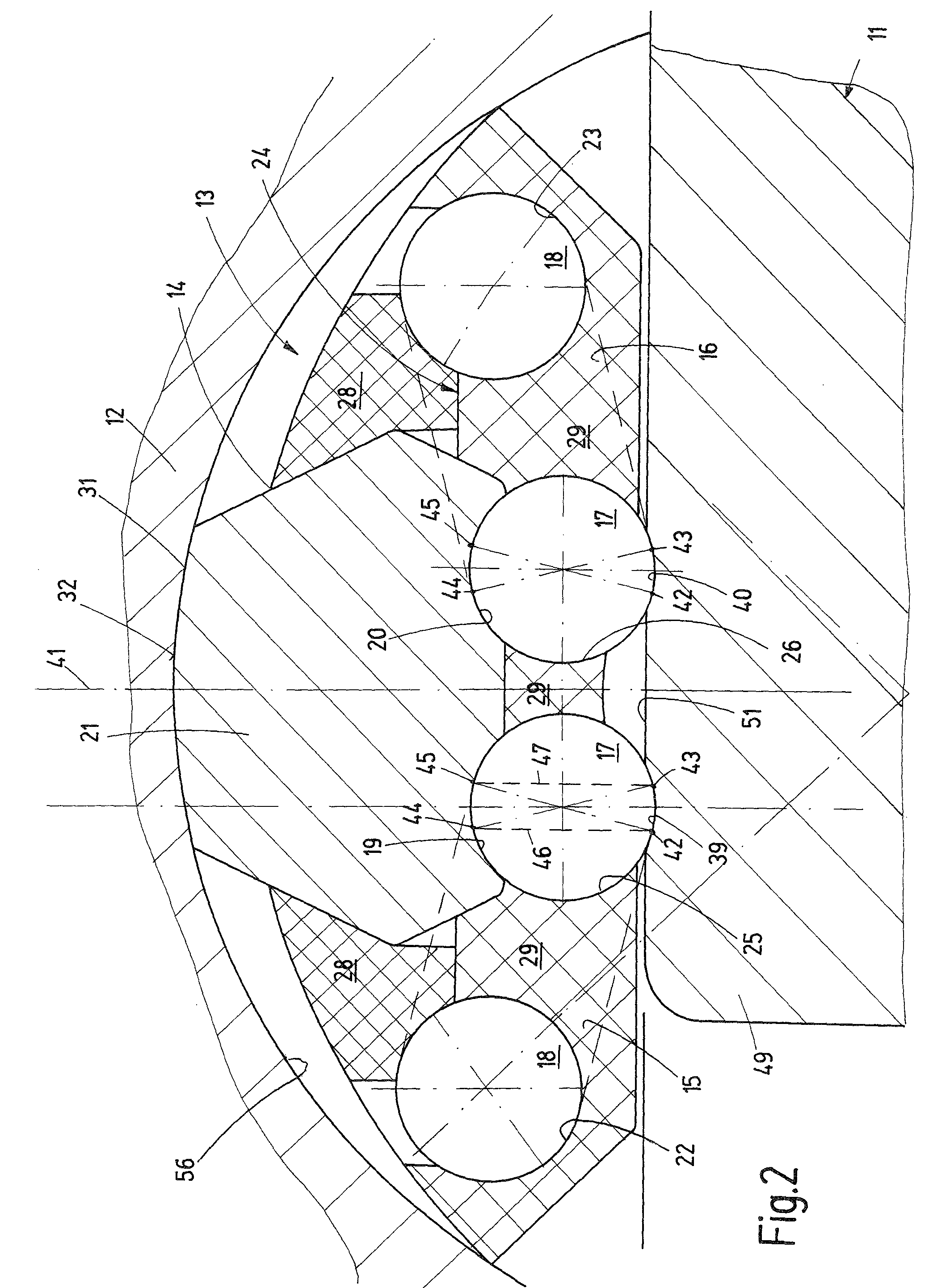
[0024]Special features of the at least one roller bearing element 30—raceway element 14 in particular—are explained in greater detail below with reference to FIGS. 1 through 9.

[0025]Linear roller bearing element 13 is designed such that it includes two endless rolling element channels 15 and 16—which transition into each other steplessly along the channel—for load-bearing rolling elements 17 and non-load-bearing rolling elements 18. In this case, rolling elements 17, 18 are composed of balls, which preferably have a relatively small diameter. Every rolling element channel 15, 16 is compo...


PUM


Abstract

A linear roller bearing element with an endless rolling element channel is composed of a carrier raceway for the load-bearing rolling elements on a carrier body, a return channel for rolling elements that are returning, and turnaround channels that connect the carrier raceway and the return channel at both ends with each other in an endless manner, the turnaround channels being bounded by end covers. The roller bearing element has two rolling element channels with two longitudinally extending carrier raceways located next to each other within a common plane and with clearance between them, on the carrier body for load-bearing rolling elements, and two assigned return channels for rolling elements that are returning, and respective turnaround channels. With a linear roller bearing guide, these roller bearing elements are located between a guide rail and a guide carriage—which is supported such that it is displaceable relative to the guide rail—in order to provide support.

Description

CROSS-REFERENCE TO A RELATED APPLICATION[0001]The invention described and claimed hereinbelow is also described in German Patent Application DE 10 2006 060 609.4 filed on Dec. 21, 2006. This German Patent Application, whose subject matter is incorporated here by reference, provides the basis for a claim of priority of invention under 35 U.S.C. 119(a)-(d).BACKGROUND OF THE INVENTION[0002]The present invention relates to a linear roller bearing element.[0003]Linear roller bearing elements of this type are used for linear roller bearing guides, with which the roller bearing elements are located between a guide rail and a guide carriage supported on the guide rail such that it is displaceable relative thereto. Roller bearing guides of this type are known and are available in diverse configurations. They are composed of a solid guide carriage, which may be moved via the rolling elements on the guide rail, relative to the guide rail. Systems are used that are known with regard for roller ...

Claims


Application Information

Patent Timeline
Patent Type & Authority Patents(United States)
IPC IPC(8): F16C29/06F16C29/04
CPCF16C29/001F16C29/0676F16C29/0669F16C29/0616
Inventor MUELLER, ARNOLD
Owner AMK ARNOLD MUELLER GMBH & CO KG
Why Eureka
Try Eureka