Lateral expandable interbody fusion cage

a fusion cage and expandable technology, applied in the field of lateral expandable interbody fusion cage, can solve the problems of less effective control of vertebral motion by redundant annular fibers, less ability to handle compression load, and thinner nucleus, and achieve the effect of promoting fusion between two vertebra

Inactive Publication Date: 2011-05-31
MILLER JIMMY D
View PDF16 Cites 239 Cited by
  • Summary
  • Abstract
  • Description
  • Claims
  • Application Information

AI Technical Summary

Benefits of technology

[0014]It is another object of the present invention to provide a LEIF cage which promotes fusion between two vertebrae.

Problems solved by technology

The nucleus becomes thinner and less able to handle compression loads.
The redundant annular fibers are less effective in controlling vertebral motion.
Disc herniation can also promote arthritis of the facet joints, which in turn may cause back pain.
Such problems may include pain in the back or legs, nerve injury, risk of future nerve injury, or spinal deformity.
Cages currently available for insertion from a posterior approach have some important weaknesses.
Large cages inserted posteriorly risk nerve injury from retracting the nerves to insert the cage or the edge of the cage during insertion, or extensive bone removal.
Revision procedures are more difficult after the facet joints have been removed.
None of these choices is ideal.

Method used


Image

  • Lateral expandable interbody fusion cage
  • Lateral expandable interbody fusion cage
  • Lateral expandable interbody fusion cage

Examples


Embodiment Construction

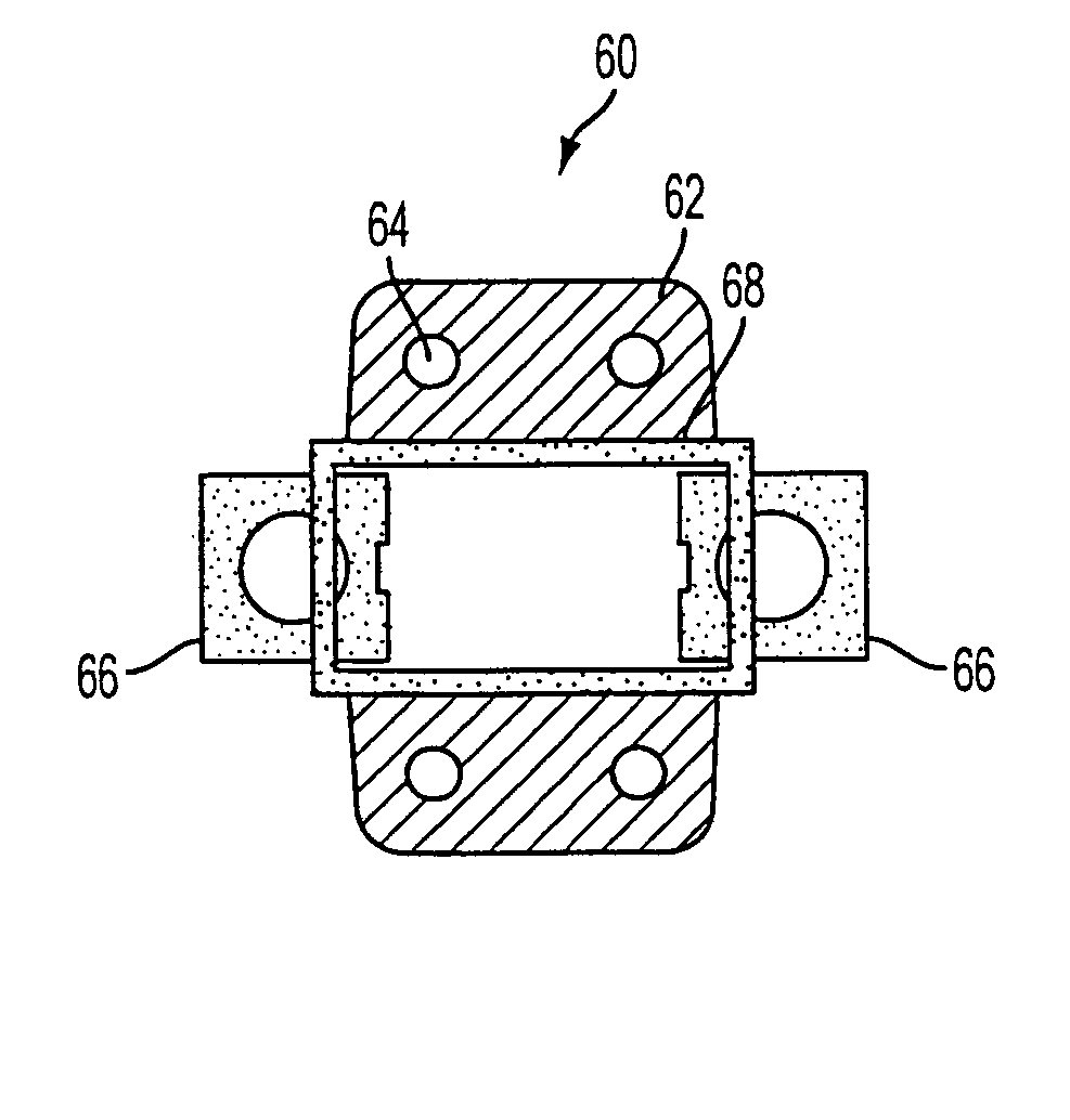
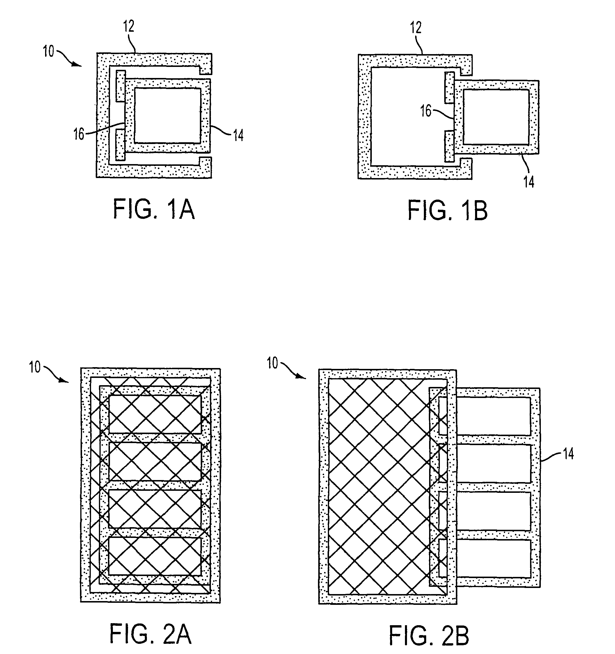
[0036]The laterally expandable interbody fusion cage of the present invention comprises an outer cage 12 and an inner cage 14 that can be inserted sideways into the outer cage 12. The inner cage 14 has a notch 16 for an expander to grip on the front of the inner cage 14. The inner cage 14 can be filled with graft material prior to insertion.

[0037]FIG. 1A shows an end view of the cage 10 as inserted, with the inner cage 14 inside of the outer cage 12. FIG. 1B shows an end view of the cage as expanded. With the cage expanded following insertion into the interspace, the outer cage 12 can be filled with graft material.

[0038]FIG. 2A shows a top view of the cage 10 as inserted. FIG. 2B shows the right top view of the cage 10 as expanded following insertion. The cage 10 can be expanded by adjusting the position of the inner cage 14 to the desired dimensions.

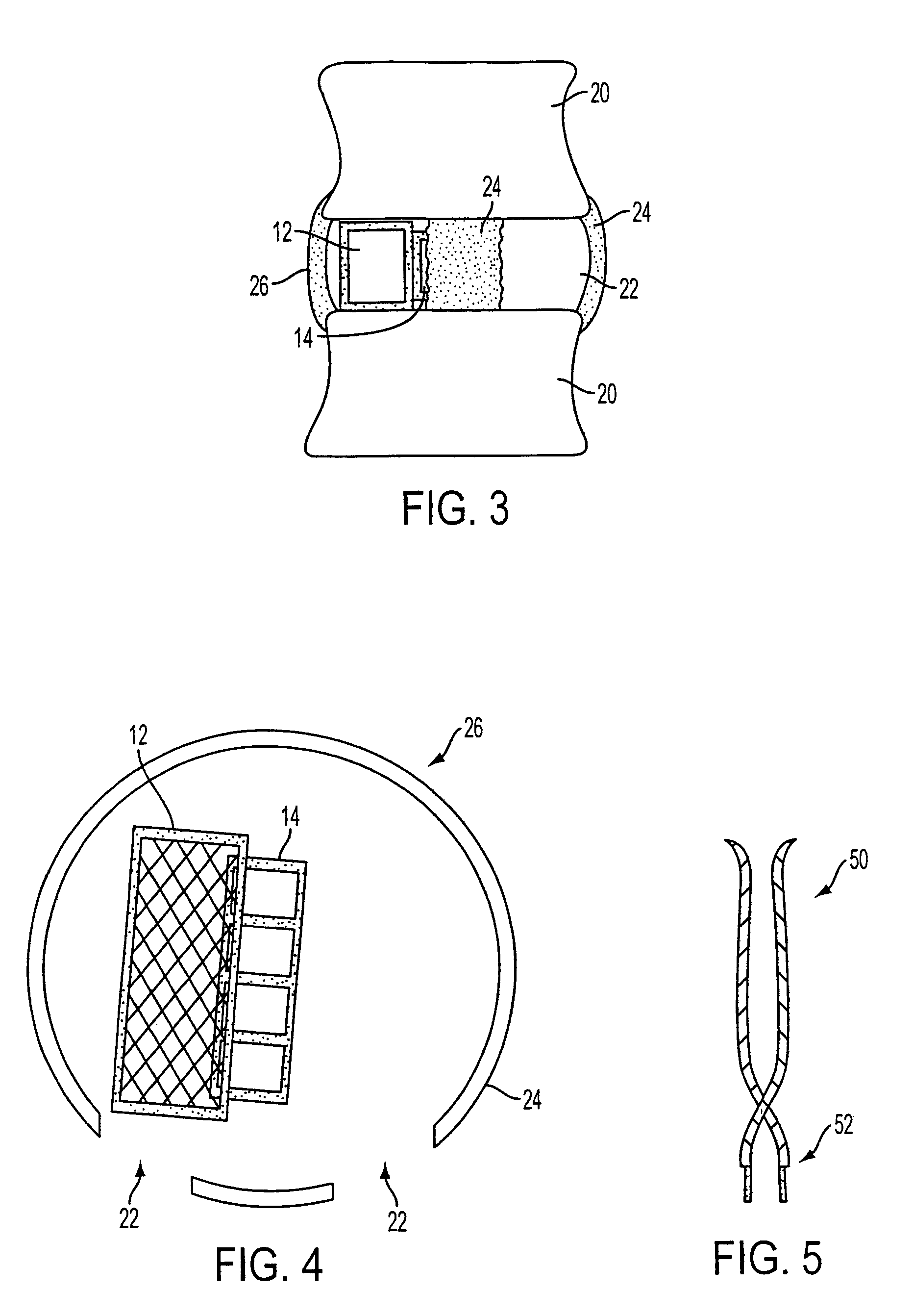
[0039]FIG. 3 is a view of two vertebral bodies 20 with a disc between them. Annular windows 22 have been created bilaterally through w...


PUM


Abstract

A lateral expandable interbody fusion cage expands laterally between two vertebrae to promote fusion between the two vertebrae. The cage includes an outer cage and at least one inner cage, with optional flanges and spikes.

Description

BACKGROUND OF THE INVENTION[0001]Eighty five percent of the population will experience low back pain at some point. Fortunately, the majority of people recover from their back pain with a combination of benign neglect, rest, exercise, medication, physical therapy, or chiropractic care. A small percentage of the population will suffer chronic low back pain. The cost of treatment of patients with spinal disorders, plus the patients' lost productivity, is estimated to be 25 to 100 billion dollars annually.[0002]Seven cervical neck, twelve thoracic, and five lumbar (low back) vertebrae form the normal human spine. Intervertebral discs reside between adjacent vertebrae with two exceptions: (1) The articulation between the first two cervical vertebrae does not contain a disc; (2) A disc lies between the last lumbar vertebra and the sacrum (a portion of the pelvis).[0003]Motion between vertebrae occurs through the disc and two facet joints. The disc lies in the front or anterior portion of...

Claims


Application Information

Patent Timeline
Patent Type & Authority Patents(United States)
IPC IPC(8): A61F2/44
CPCA61F2/4455A61F2/4611A61F2230/0082A61F2/447A61F2002/2835A61F2002/30133A61F2002/30266A61F2002/30578A61F2002/30579A61F2002/4475A61F2002/448A61F2002/4622A61F2002/4628A61F2230/0015A61F2/4465A61F2002/30593
Inventor MILLER, JIMMY D.
Owner MILLER JIMMY D
Why Eureka
Try Eureka