Light emitting display device, plasma display device and phosphor particles

a technology of display device and phosphor particle, which is applied in the direction of discharge tube luminescnet screen, cellulosic plastic layered product, natural mineral layered product, etc., can solve the problems of deteriorating fluorescence particles, reduce and reduce the luminance of fluorescence particles , the effect of reducing the number of ion defects and lattice defects

Inactive Publication Date: 2011-05-31
PANASONIC CORP
View PDF25 Cites 2 Cited by
  • Summary
  • Abstract
  • Description
  • Claims
  • Application Information

AI Technical Summary

Benefits of technology

According to the present invention, in the reformed layer of a fluorescence particle, which covers the range from the surface of the fluorescence particle through a depth of 20 nm, at least one element selected from the group consisting of Al, Mg, Ca, Ba, Sr and Y has a local maximum in the concentration profile in the depth direction. Thus, the number of ion defects and lattice defects can be reduced in the vicinity of the surface of the fluorescence particle, and therefore, the fluorescence particle can withstand the ion bombardment so well that its crystal structure is hardly affected. As a result, the decrease in the luminance of the fluorescence particle can be minimized. In addition, at least one element selected from the group consisting of Al, Mg, Ca, Ba, Sr and Y forms an ion bond with oxygen in the reformed layer, and is likely to emit electrons. As a result, the loss of electrons that have drifted due to the decrease in electrical discharge voltage or the interval between the barrier ribs can be compensated for, and the luminance can be increased. Consequently, the present invention provides a high-definition plasma display panel that can minimize the decrease in the luminance of the fluorescence while the panel is being driven, will never cause any color unevenness or image persistence, and will have a significantly extended life while dissipating much less power.

Problems solved by technology

For that reason, the fluorescence layer is exposed to the plasma and cations in the plasma will collide against the fluorescence particles, thus deteriorating the fluorescence particles.

Method used


Image

  • Light emitting display device, plasma display device and phosphor particles
  • Light emitting display device, plasma display device and phosphor particles
  • Light emitting display device, plasma display device and phosphor particles

Examples


example 1

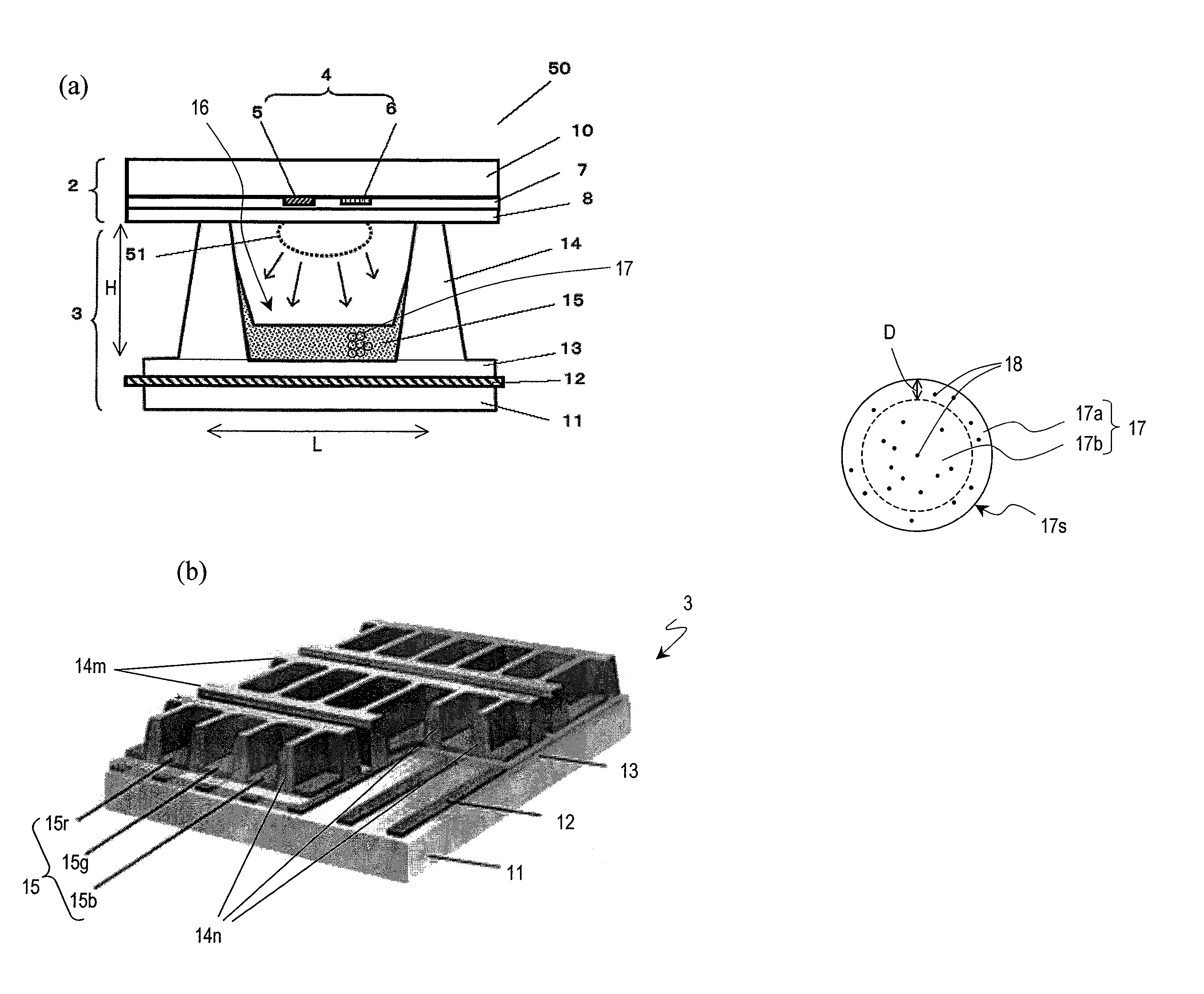
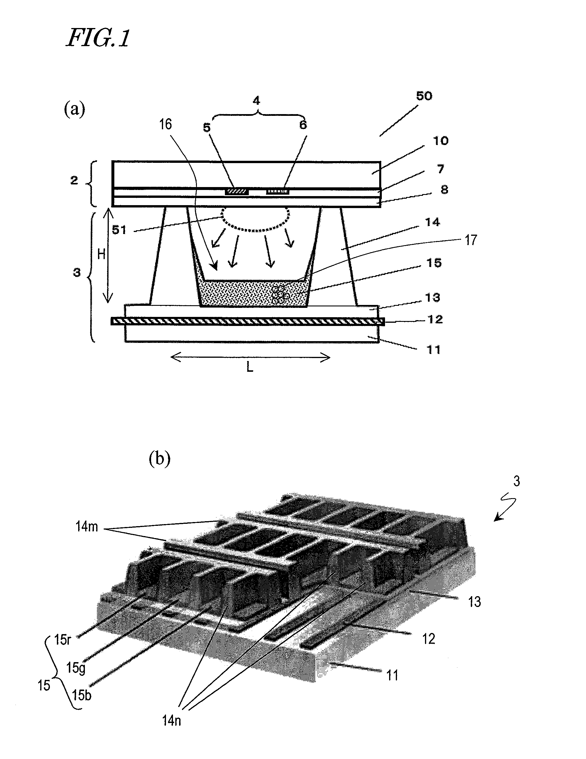
Fluorescence particles were made by the method described above using the fluorescent material and organometallic compounds shown in the following Table 1. A retailed material was used as the fluorescent material. Xylene was used as a solvent to dissolve the organometallic compound, of which the concentration was adjusted in advance to 0.5 mol / L.

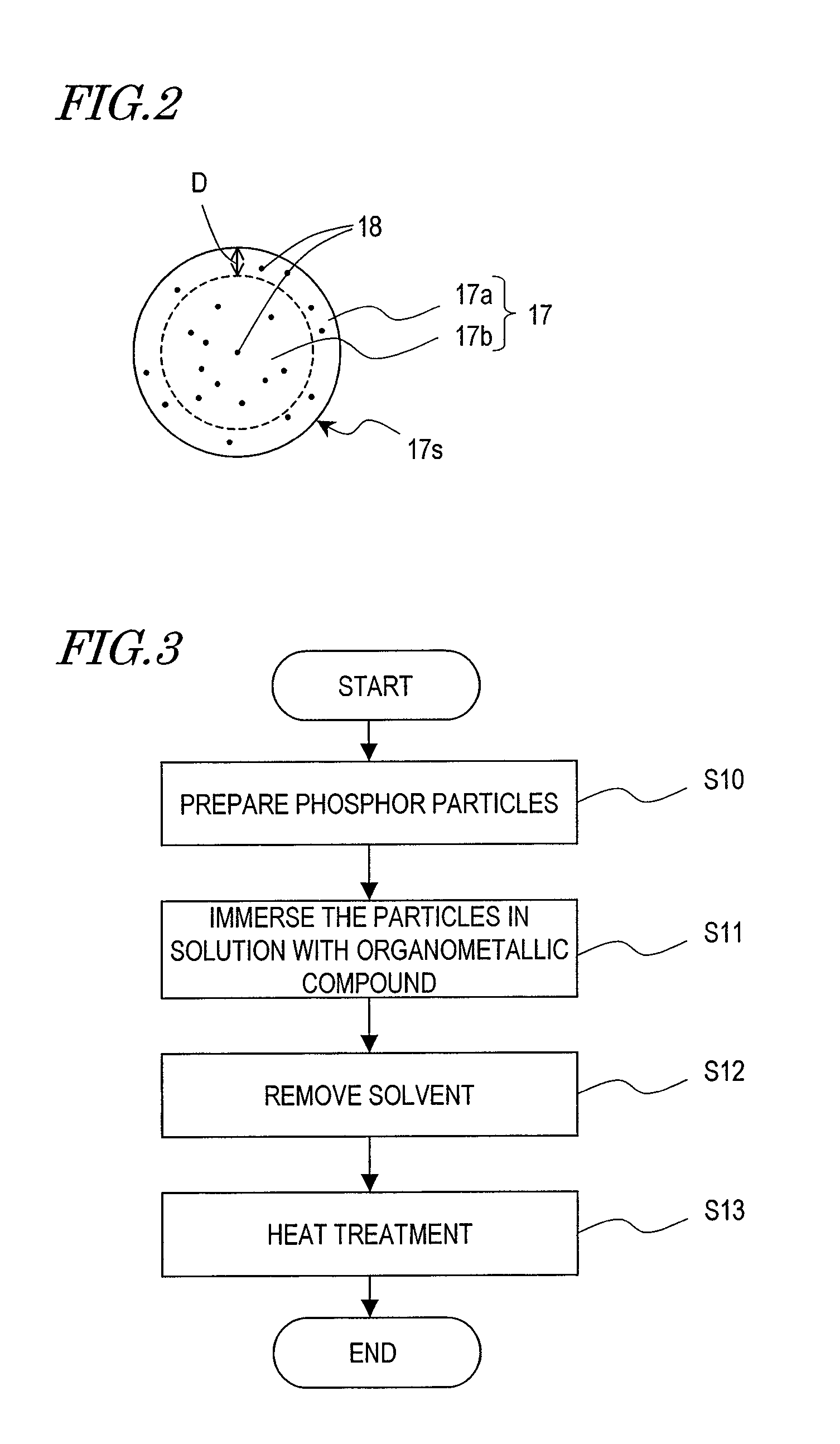
Next, 1.0 part by weight of fluorescence powder was mixed in the air with 0.2 parts by weight of organometallic compounds and 2.0 parts by weight of xylene as a diluent and the mixture was stirred up for about 30 minutes in a glass container. Thereafter, the mixture was filtered to separate fluorescence particles. Subsequently, the fluorescence was kept heated to about 150° C. and dried in the air for an hour. And then the dried fluorescence particles were loaded into a ceramic sheath and thermally treated at about 600° C. for 10 minutes in the air. This process step will be referred to herein as an “organometallic process on fluorescence par...

example 2

The present inventors fabricated a plasma display panel using the fluorescence particles of the present invention and evaluated its characteristics.

Fluorescence particles in the respective colors of R, G and B were made by the method described above using the fluorescent materials and organometallic compounds shown in the following Table 2. Retailed materials were used as the fluorescent materials. Xylene was used as a solvent to dissolve the organometallic compound, of which the concentration was adjusted in advance to 0.5 mol / L.

TABLE 2Organometallic compoundAddedinpartOrganometallicNumberNumberSampleFluorescencebycompound andofofNo.R (red)G (green)B (blue)weightits amountmetalscarbonsB1(Y, Gd)BO3:Eu(Y, Gd)BO3:TbBaMgAl10O17:Eu1Al ethylacetate112diisopropylate(0.2)B2(Y, Gd)BO3:Eu(Y, Gd)BO3:Tb andBaMgAl10O17:Eu1Al acetoalkoxy128ZN2SiO4:Mndiisopropylate(0.2)B3(Y, Gd)BO3:Eu(Y, Gd)BO3:Tb andBaMgAl10O17:Eu1Al115and YVO4:EuZn2SiO4:Mnacetylacetone(0.2)B4(Y, Gd)BO3:Eu(Y, Gd)BO3:Tb andBaMgAl...

example 3

The present inventors added the organometallic compound with its concentration varied to find its preferred concentration. The results are as follows.

In the first specific example described above, samples were prepared by mixing together 1.0 part by weight of fluorescence powder, 0.2 parts by weight of organometallic compound, and 2.0 parts by weight of xylene as a diluent. In this specific example, samples were prepared with the amount of the organometallic compound added varied between 0.05 and 5.0 parts by weight as shown in the following Table 3, and variations in the emission intensity of the fluorescence particle irradiated with a vacuum ultraviolet ray (with a wavelength of 147 nm) before and after the ion bombardment were estimated. For this experiment, a blue fluorescence BaMgAl10O17: Eu and Mg octylate were used as a fluorescence and an organometallic compound, respectively.

TABLE 3AddedAddedininpartOrgano-partsNumberNumberSamplebymetallicbyofofNo.Fluorescenceweightcompound...


PUM

PropertyMeasurementUnit
temperatureaaaaaaaaaa
center wavelengthaaaaaaaaaa

Abstract

A fluorescence particle 17 according to the present invention is used for a light emitting display device and is made of a fluorescent material. The fluorescent material has at least one element 18 selected from the group consisting of Al, Mg, Ca, Ba, Sr and Y. Within a range 17a from the surface 17s of the fluorescence particle through a depth of 20 nm, the at least one element 18 has a local maximum of its concentration profile in the depth direction.

Description

TECHNICAL FIELDThe present invention relates to a light emitting display device such as a plasma display panel for use to present an image on a TV, for example, and also relates to a fluorescence particle for use in such a device.BACKGROUND ARTIn recent years, there is a growing demand for high-definition TVs with high image quality and a big screen. A plasma display panel (PDP) not only has these advantageous features but also is thin and lightweight as well. For that reason, plasma TV sets that use a plasma display panel have attracted a lot of attention these days.A plasma display panel conducts a display operation in full colors by adding together the so-called “three primary colors”. To get such a full-color display operation done, a fluorescence layer that emits radiations in red (R), green (G) and blue (B) is provided in the barrier rib of a PDP. The fluorescence particles that form the fluorescence layer are excited by an Xe resonance beam with a center wavelength of 147 nm,...

Claims


Application Information

Patent Timeline
Patent Type & Authority Patents(United States)
IPC IPC(8): H01J17/49H01J17/16
CPCC09K11/595C09K11/643C09K11/7734C09K11/7777C09K11/778C09K11/7794C09K11/7795C09K11/7797H01J11/12H01J11/42C09K11/7787Y10T428/2993C09K11/77
Inventor HONDA, YOSUKEUENO, IWAONISHIYAMA, SEIJI
Owner PANASONIC CORP
Why Eureka
Try Eureka