Method and apparatus for impact detection and prioritization of impact information transmitted to a receiving station

Active Publication Date: 2011-06-07
PERATON INC
View PDF8 Cites 18 Cited by
  • Summary
  • Abstract
  • Description
  • Claims
  • Application Information

AI Technical Summary

Benefits of technology

[0009]Accordingly, it is an object of the present invention to prioritize transmission of sensor informatio

Problems solved by technology

However, the related art system (without additional sensors) provides information pertaining only to the impact location (e.g., by measuring the optical fiber sever sequence and transmitting that data to a remote recei

Method used


Image

  • Method and apparatus for impact detection and prioritization of impact information transmitted to a receiving station
  • Method and apparatus for impact detection and prioritization of impact information transmitted to a receiving station
  • Method and apparatus for impact detection and prioritization of impact information transmitted to a receiving station

Examples


Example

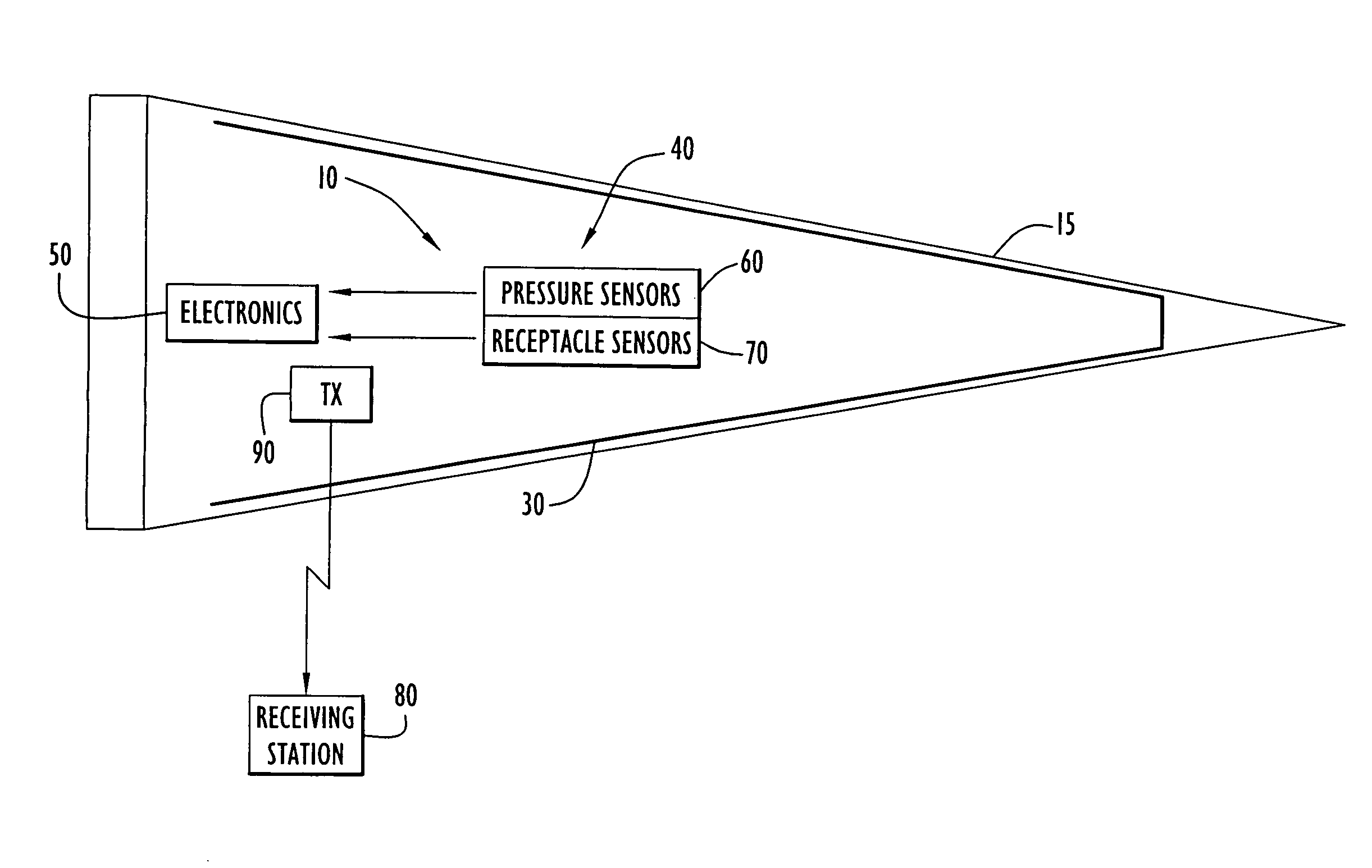
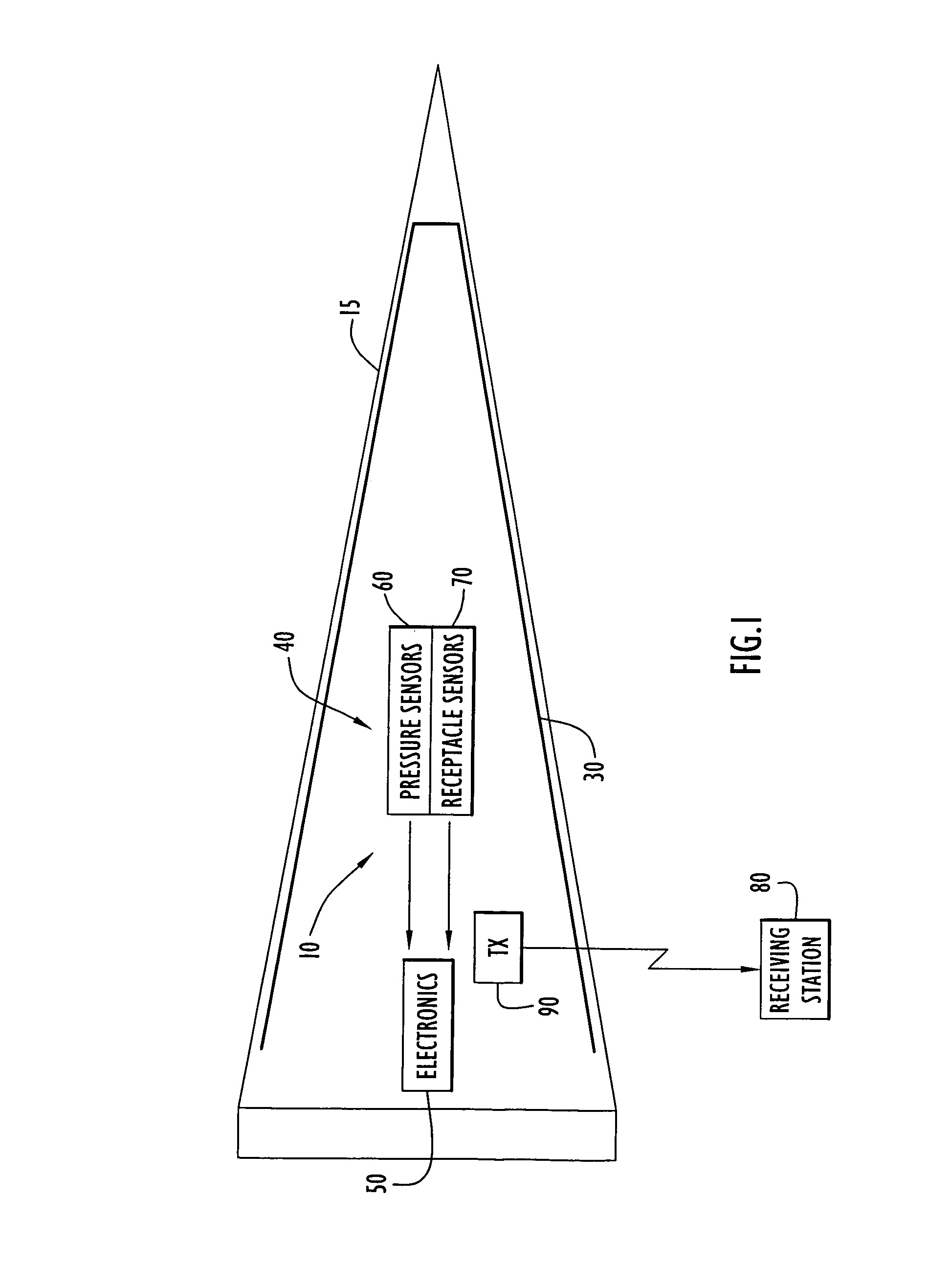
[0021]The present invention pertains to detection of impacts and subsequent effects on a target object and prioritizing transmission of information from various sensors to a receiving station. By way of example only, the present invention may be applied to ballistic missile defense flight target testing to detect and assess the nature of a missile impact (e.g., missile accuracy, lethality of an impact, damage to a target object, etc.).

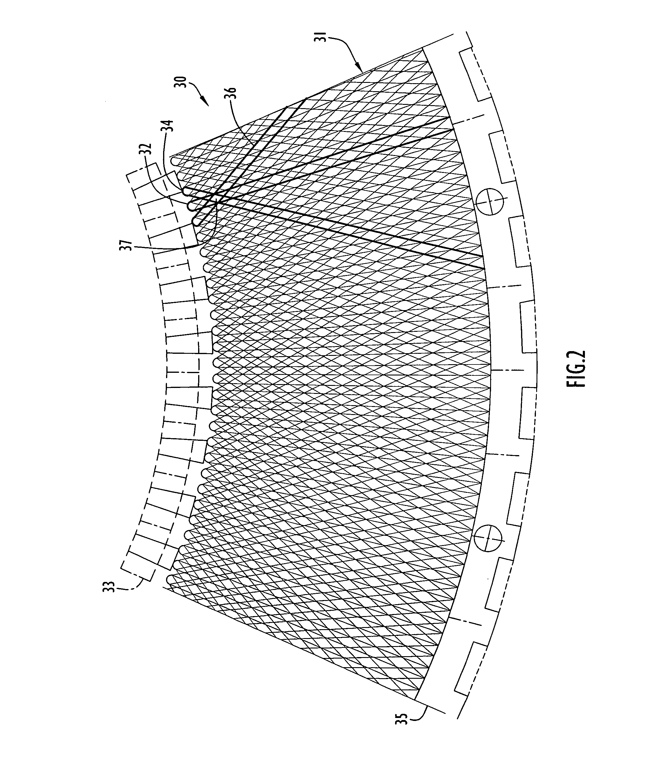
[0022]An impact detection system according to the present invention is illustrated in FIG. 1. Specifically, an impact detection system 10 is disposed within an exemplary target object 15 (e.g., missile target, target vehicle, etc.). The target object typically includes a housing defining an interior space for the impact detection system and other articles. The impact detection system includes impact sensor 30, sensor unit 40, an electronics package 50 and a transmitter 90. The impact sensor is arranged in the form of a grid that is typically disposed p...


PUM


Abstract

An impact detection system according to the present invention includes an impact sensor, damage sensors and an electronics package. The impact sensor includes a fiber optic grid preferably attached to a target object to detect impact locations on the target. The damage sensors measure damage sustained by the object, while the electronics package monitors the fiber optic grid, records the impact location and sends information pertaining to the impact location and target damage through a telemetry link with limited bandwidth to a receiving station. In order to ensure transmission of desired information, the electronics package allocates telemetry bandwidth to sensor information most relevant to impact location and target damage to enable transmission in the limited time interval available prior to target destruction or impact detection system disablement. This is accomplished by dynamically allocating reporting priority to different sensors during an impact.

Description

STATEMENT REGARDING FEDERALLY SPONSORED RESEARCH OR DEVELOPMENT[0001]The U.S. Government may have a paid-up license in this invention and the right in limited circumstances to require the patent owner to license others on reasonable terms as provided by the terms of the contract.BACKGROUND OF THE INVENTION[0002]1. Technical Field[0003]The present invention pertains to impact detection on a target object. In particular, the present invention pertains to detection of impacts and subsequent effects on a target object and prioritizing transmission of information from various sensors to a receiving station.[0004]2. Discussion of Related Art[0005]Various applications may employ detection of impacts on an object to assess damage, structural integrity or other properties of the object affected by an impact. The impact detections may further provide information relating to properties of an article impacting the object. For example, ballistic missile defense flight target testing employs impa...

Claims


Application Information

Patent Timeline
IPC IPC(8): G01P15/00
CPCF42B30/006F42B12/365
Inventor PADEREWSKI, GARYLESAGE, JOHN
Owner PERATON INC
Why Eureka
Try Eureka