Piezoelectric fluid atomizer apparatuses and methods

a technology of atomizer and fluid, applied in the direction of liquid spraying apparatus, spraying nozzle, moving spraying apparatus, etc., can solve the problems of high power consumption of conventional atomizers, inability to provide atomized fluid, ac adaptor, etc., and achieve the effect of low power consumption

Inactive Publication Date: 2011-06-07
HONG KONG PIEZO
View PDF28 Cites 35 Cited by
  • Summary
  • Abstract
  • Description
  • Claims
  • Application Information

AI Technical Summary

Benefits of technology

[0006]The present invention generally comprises methods and apparatuses for providing atomized fluids. In particular, an apparatus of the present invention is compact and functions with low power consumption. Embodiments of the present invention comprise fluid atomizers that can be powered by AC current, or alternatively DC current provided by, including but not limited to, batteries and many other DC current sources. Aspects of the apparatus of the present invention may be controlled remotely. By using a timing means, the apparatus may be activated at any time to provide, for example, atomized fragrance, air freshener, or medicinal agents. Embodiments of the apparatus comprise piezoelectric atomizers comprising symmetric or nonsymmetrical piezo components. Embodiments of piezoelectric atomizers comprise a piezo component defining an opening that is bonded to a metal plate defining a mist reservoir. More specifically, the mist reservoir may define a plurality of apertures (or holes) oriented substantially perpendicular, and the opening of the piezo component may be located above the mist reservoir.

Problems solved by technology

Since the liquid reservoir of a conventional atomizer is of an open design, the liquid must be maintained at a higher volume and level, with the ultrasonic vibrating component unavoidably requiring a larger sonic wave exciter surface area to generate a sonic field that is sufficient to atomize the liquid in the reservoir.
As such, the design of conventional atomizers generally requires high power consumption and AC adaptors.
Though atomizers may be actuated by hand operation, such atomizers are for personal use only and cannot be used to provide atomized fluids remotely.
There are also other design elements that have hampered atomizer development and wider utilization in has not occurred.

Method used


Image

  • Piezoelectric fluid atomizer apparatuses and methods
  • Piezoelectric fluid atomizer apparatuses and methods
  • Piezoelectric fluid atomizer apparatuses and methods

Examples


Embodiment Construction

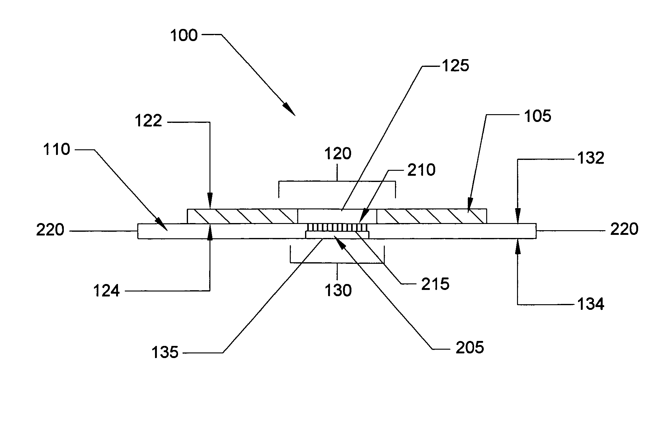
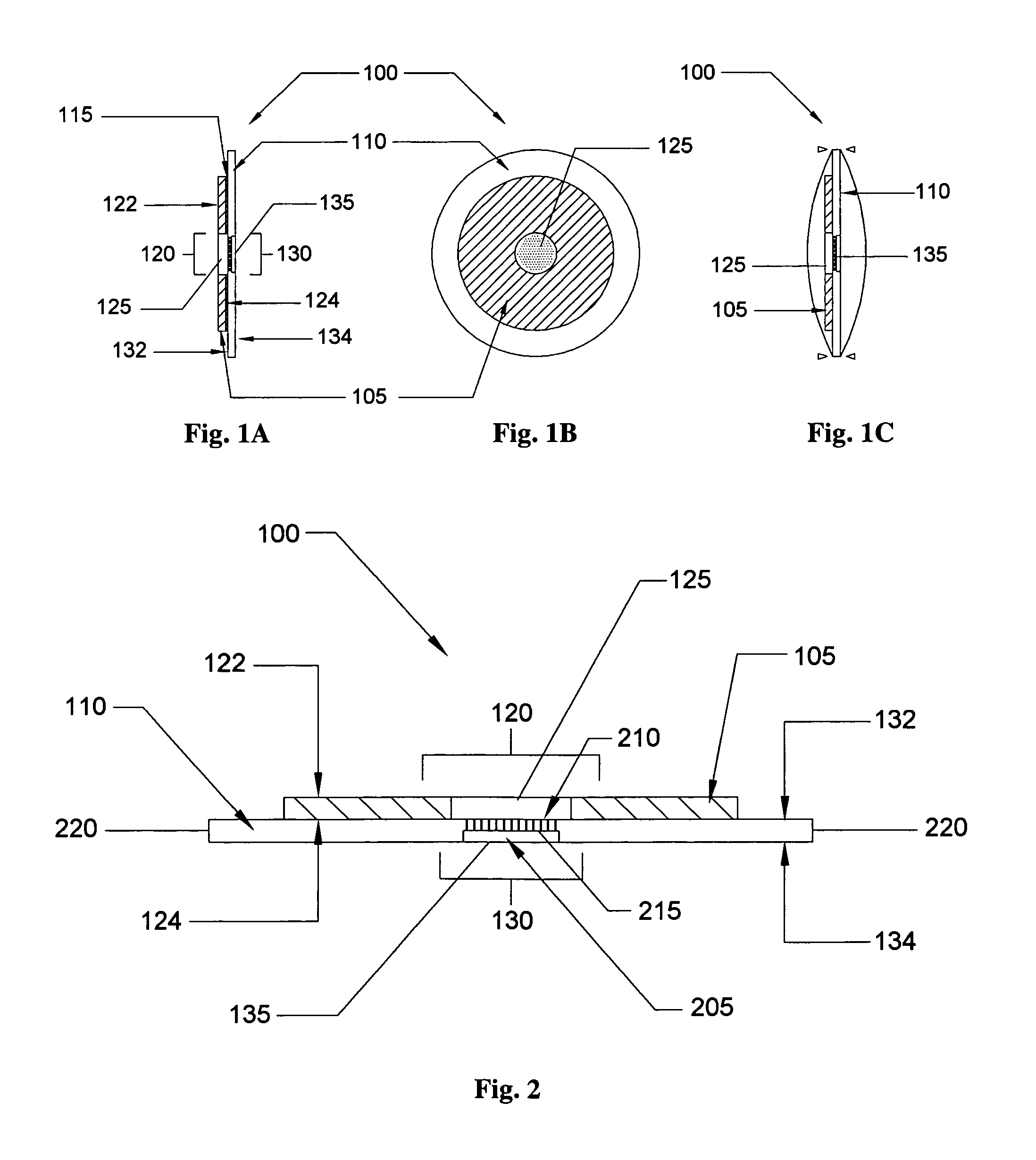
[0029]The present invention comprises methods and apparatuses for atomizing fluids. An apparatus of the present invention comprises a piezo ceramic disc attached (or coupled) to a metal diaphragm, for example, by gluing the piezo disc to the metal. The attachment of a piezo ceramic to one side of a metal plate or diaphragm is referred to as nonsymmetrical herein. The present invention comprises fluid atomizers made with nonsymmetrical piezo components. One aspect of an apparatus of the present invention comprises a ring-shaped piezo ceramic glued onto a metallic diaphragm. Prior art nonsymmetrical piezo components comprise a smaller diameter piezo disc attached to one side of a larger diameter metallic plate or diaphragm.

[0030]An aerosol apparatus of the present invention comprises a chamber and a mist reservoir formed in a metal steel plate or diaphragm. When the nonsymmetrical component is actuated, liquid is provided through the tapered holes in the roof of the mist reservoir. Th...


PUM


Abstract

Piezo aerosol and ultrasonic atomizer apparatuses are disclosed. In some embodiments, a piezo aerosol apparatus may comprise a piezo component defining an opening bonded to a metal plate defining a mist reservoir. The mist reservoir may define a plurality of apertures (or holes) orientated substantially perpendicular, and the opening of the piezo component may be located above the mist reservoir. The piezo aerosol apparatus generally defines a non-symmetric compound, while the ultrasonic atomizer comprises a piezo component and metal plate of substantially the same diameter in length. Other embodiments are also claimed and disclosed.

Description

TECHNICAL FIELD[0001]The present invention relates to piezoelectric fluid atomizers. More particularly, the present invention relates to piezoelectric fluid atomizers utilizing a tunnel and plateau formation.BACKGROUND OF THE INVENTION[0002]Piezoelectric materials have the unusual characteristics that when subjected to a mechanical force, the materials, particularly crystalline minerals, become electrically polarized, and when the materials are subjected to an electric field, the material lengthens or shortens according to the polarity of the field and in proportion to the strength of the field. Due to these characteristics, piezoelectric materials have been used in a wide range of applications. For example, piezoelectric materials have been used in sensing applications, such as force or displacement sensors, and applications of materials with the inverse piezoelectric effect include actuation applications, such as in motors and devices that precisely control positioning, and in gen...

Claims


Application Information

Patent Timeline
Patent Type & Authority Patents(United States)
IPC IPC(8): B05B1/08B05B3/04
CPCB05B17/0646B05B17/0684A61M11/00B05B1/06B05B7/06
Inventor NG, LAP LEUNG
Owner HONG KONG PIEZO
Why Eureka
Try Eureka