Method for controlling a compressed air installation comprising several compressors, control box applied thereby and compressed air installation applying this method

a technology of compressed air and compressors, applied in the direction of fluid pressure control, instruments, nuclear elements, etc., can solve the problem that the method is not suitable for combining more than two different types of compressors in a single compressed air installation

Active Publication Date: 2011-06-07
ATLAS COPCO AIRPOWER NV
View PDF7 Cites 52 Cited by
  • Summary
  • Abstract
  • Description
  • Claims
  • Application Information

AI Technical Summary

Benefits of technology

[0016]Such a compressed air installation with three different types of compressor...

Problems solved by technology

An additional disadvantage is that such a method is not suitable for combining ...

Method used


Image

  • Method for controlling a compressed air installation comprising several compressors, control box applied thereby and compressed air installation applying this method
  • Method for controlling a compressed air installation comprising several compressors, control box applied thereby and compressed air installation applying this method
  • Method for controlling a compressed air installation comprising several compressors, control box applied thereby and compressed air installation applying this method

Examples


Embodiment Construction

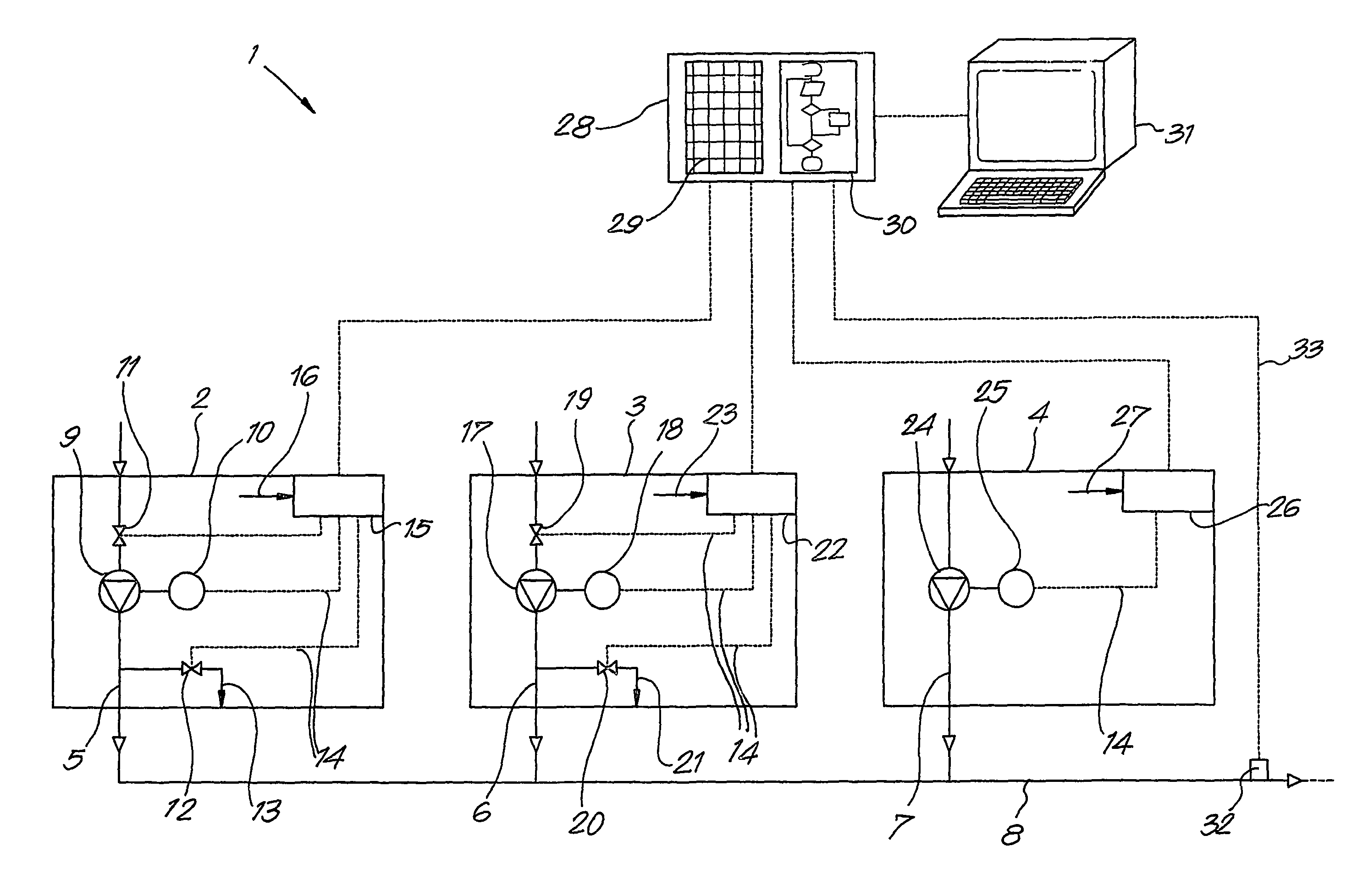
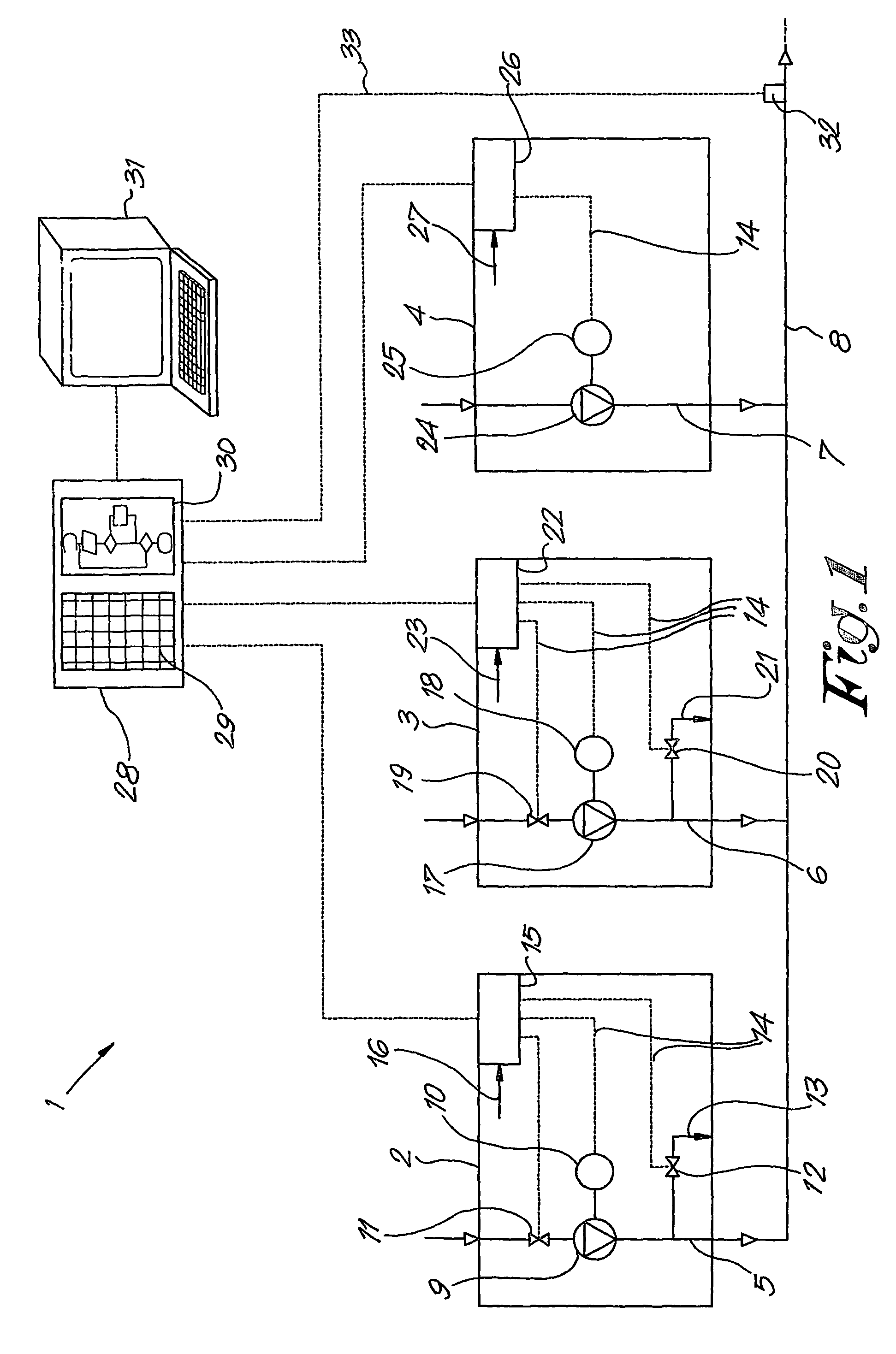
[0022]In FIG. 1, a compressed air installation 1 is represented by way of example comprising three different compressors, in particular a first compressor 2 of the ‘loaded / unloaded’ type, a second compressor 3 of the turbo type and a third compressor 4 of the type with a variable rotational speed, whereby these compressors are connected to a single compressed air network 8 with their respective outlets 5-6-7.

[0023]The compressor 2 of the ‘loaded / unloaded’ type in this case consists of a compressor element 9 which is coupled to an electric motor 10.

[0024]In the inlet of the compressor element 9 is provided a controlled inlet valve 11 with an open and a closed position, whereas a controlled exhaust valve 12 is provided in the exhaust 5 with an outlet 13 which opens into the ambient air.

[0025]The motor 10, the inlet valve 11 and the exhaust valve 12 are connected to a control element 15 by means of electric conductors 14 which can give control orders to start the motor 10 and to stop i...


PUM


Abstract

Method for adjusting a compressed air installation using several electrically driven compressors of what is called the “loaded/unloaded” type and/or the turbo compressor type and/or the compressor type with variable rotational speed, wherein these compressors are each connected to a single compressed air network with their outlets, and wherein use is made of a control box which makes it possible to adjust the pressure in the compressed air network around a target pressure to be set. The adjustment takes place by controlling the flow of one or several of the compressors, in particular in order to increase the overall flow supplied by the compressors when the pressure drops too much, and in order to lower the overall supplied flow when the pressure becomes too high.

Description

BACKGROUND OF THE INVENTION[0001]A. Field[0002]The present invention concerns a method for controlling a compressed air installation comprising several compressors.[0003]B. Related Technology[0004]Such compressed air installations comprising several compressors are already known, whereby one or two different types of compressors at the most are combined, which compressors are connected to a single compressed air network with their respective outlets and which are switched on and off in cascade, each at a different switching pressure in order to prevent that several compressors would be switched on and off simultaneously, which would result in enormous fluctuations in the compressed air network.[0005]Such a method for controlling the compressors in a compressed air installation comprising several compressors is disadvantageous in that the overall flow and the pressure in the compressed air network may nevertheless still undergo large fluctuations.[0006]A related disadvantage is that,...

Claims


Application Information

Patent Timeline
IPC IPC(8): G05D16/00F01D17/08F04B41/06F04C28/02G05D16/20
CPCF04B41/06G05D16/2073F04C28/02Y02B30/70F04B49/065F04B49/06F04B49/22F04B2205/03F05B2210/12F05B2270/301Y10S417/00
Inventor PETTERSSON, JOHAN GEORG URBAN
Owner ATLAS COPCO AIRPOWER NV
Why Eureka
Try Eureka