Control circuit and control method for charge pump circuit

a control circuit and charge pump technology, applied in the direction of dc-dc conversion, power conversion systems, instruments, etc., can solve the problems of increasing circuit area and increasing output voltage fluctuation, and achieve the effect of reducing power consumption and suppressing output voltage fluctuation

Inactive Publication Date: 2011-06-07
ROHM CO LTD
View PDF18 Cites 41 Cited by
  • Summary
  • Abstract
  • Description
  • Claims
  • Application Information

AI Technical Summary

Benefits of technology

The present invention has been made in order to solve such a problem. It is a general purpose of the present invention to provide a control circuit for a charge pump circuit, which is capable of suppressing fluctuation of the output voltage with reduced power consumption.
Such an embodiment is capable of reducing fluctuation of the output voltage in a state in which the output voltage is stabilized at a target value. Furthermore, such an embodiment reduces power consumption by the control circuit.
With each of such voltage / current conversion circuits, the output voltage can be rapidly raised. Furthermore, such an arrangement stabilizes the output voltage around the target value, as well as reducing power consumption.

Problems solved by technology

An arrangement in which the driving state of a charge pump circuit is switched using a comparator has a problem of increased fluctuation of the output voltage.
An arrangement in which the number of comparators is increased in order to suppress the fluctuation of the output voltage has another problem of an increased circuit area.

Method used


Image

  • Control circuit and control method for charge pump circuit
  • Control circuit and control method for charge pump circuit
  • Control circuit and control method for charge pump circuit

Examples


Embodiment Construction

The invention will now be described based on preferred embodiments which do not intend to limit the scope of the present invention but exemplify the invention. All of the features and the combinations thereof described in the embodiment are not necessarily essential to the invention.

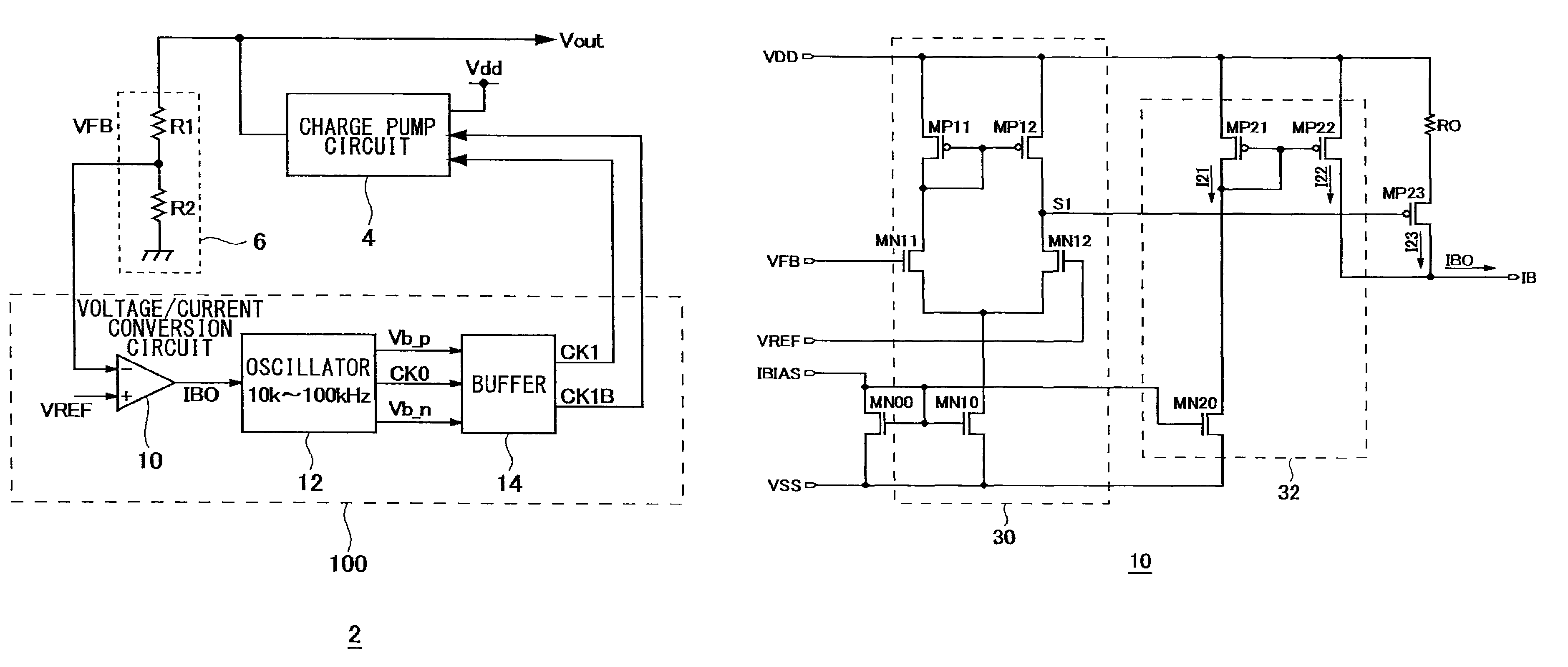
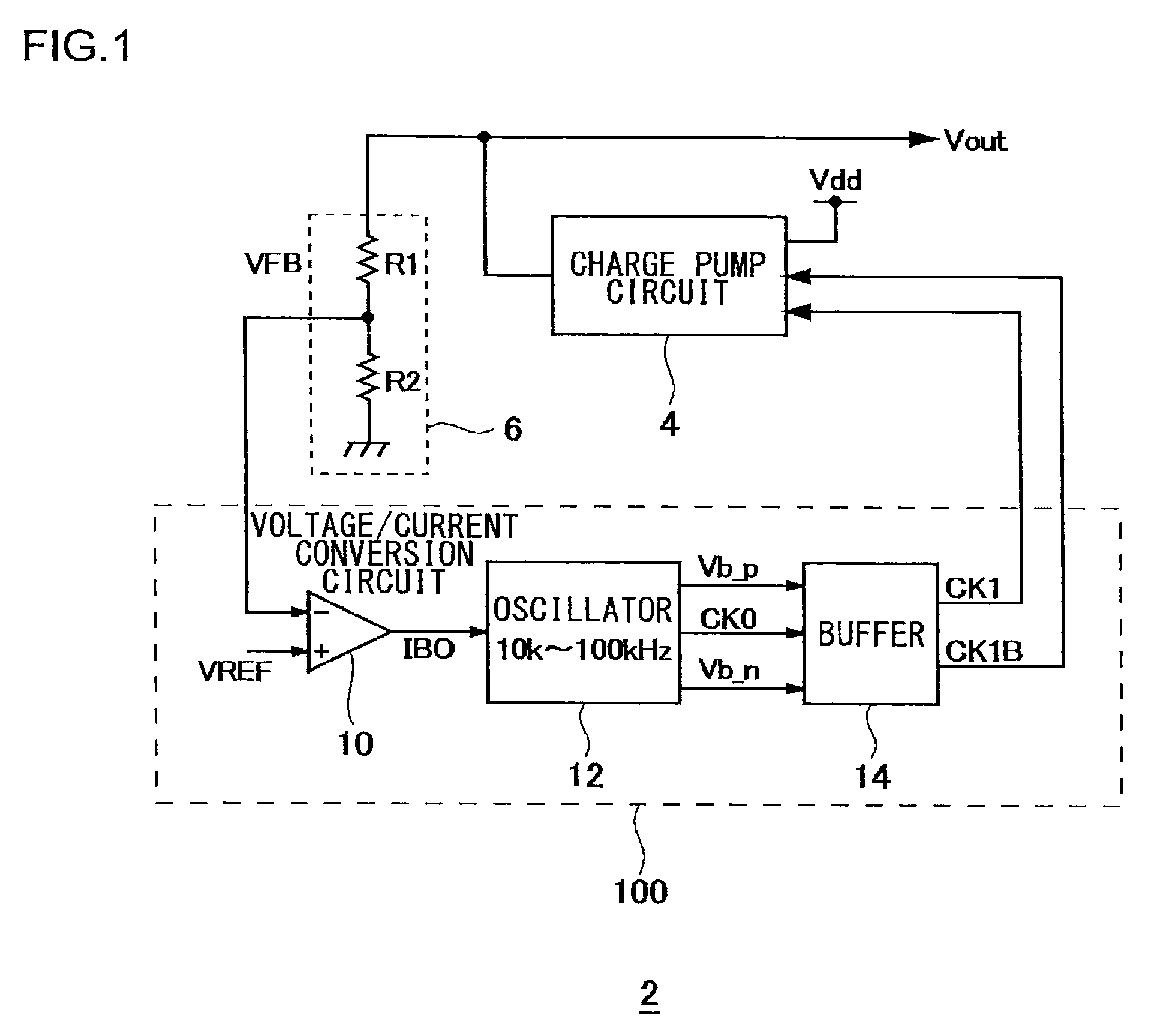
FIG. 1 is a block diagram which shows a configuration of a power supply circuit 2 according to an embodiment. The power supply circuit 2 includes a charge pump circuit 4, a voltage divider circuit 6, and a control circuit 100.

The control circuit 100 is driven by supplying a gate clock CK1 and an inverted gate clock CK1B to the charge pump circuit 4. The charge pump circuit 4 boosts the power supply voltage Vdd with a predetermined step-up ratio, and outputs the output voltage Vout. The output voltage Vout is supplied to an unshown load. The voltage divider circuit 6 includes resistors R1 and R2, and divides the output voltage Vout so as to output a feedback voltage VFB according to the output voltage Vou...


PUM


Abstract

A charge pump circuit is provided. A voltage / current conversion circuit compares a feedback voltage that corresponds to the output voltage of the charge pump circuit with a predetermined reference voltage, and generates a bias current that corresponds to the difference therebetween. An oscillator oscillates at a frequency that corresponds to the bias current. A buffer is biased by the bias current, and supplies a gate clock to the charge pump circuit based upon a clock signal output from the oscillator, thereby driving the charge pump circuit.

Description

BACKGROUND OF THE INVENTION1. Field of the InventionThe present invention relates to a charge pump circuit.2. Description of the Related ArtBattery-driven electronic devices such as cellular phones, PDAs (Personal Digital Assistants), etc., mount a circuit component which requires higher voltage than the output voltage of a battery (battery voltage). In order to supply a suitable power supply voltage to such a circuit component, a booster circuit such as a charge pump circuit, switching regulator, or the like, is employed.In a case in which a charge pump circuit is mounted on a battery-driven electronic device, in order to drive such a device for a long time, it is desirable that the charge pump circuit and the control circuit thereof operate with reduced power consumption. Examples of such techniques which have already been proposed include: a technique in which a comparator judges whether or not the output voltage of the charge pump circuit has reached a predetermined voltage, and...

Claims


Application Information

Patent Timeline
Patent Type & Authority Patents(United States)
IPC IPC(8): G05F1/10
CPCH02M3/073
Inventor SAITOH, SHINICHIYAMASHIRO, YO
Owner ROHM CO LTD
Why Eureka
Try Eureka