
High efficiency low power capacitor charged DC driver

a dc driver and capacitor technology, applied in the direction of electric variable regulation, process and machine control, instruments, etc., can solve the problems of difficult control of controlled half wave rectification, failure to provide good power efficiency, etc., to avoid excessive emi or rfi emissions and facilitate high-efficiency operation.

Active Publication Date: 2011-06-14
SAVANT TECH LLC
View PDF23 Cites 8 Cited by
  • Summary
  • Abstract
  • Description
  • Claims
  • Application Information

AI Technical Summary

Benefits of technology

The invention is a device that converts AC power into a low power DC output for powering a light source. It includes a circuit that reduces the AC output to a lower level using a capacitive divider. A rectifier then converts the divided AC output into a DC output. The DC output is then sent to one or more light sources. The device also includes a linear regulator that controls the current flow through a series circuit, which includes the light source(s). The linear regulator can be adjusted for dimming or soft starting. The device is designed to be highly efficient and can operate without excessive emissions.

Problems solved by technology

Driver circuits for powering such light sources from AC power supplies have thus far typically included multiple power conversion stages and have failed to provide good power efficiency.
Attempts to improve efficiency by capacitor charging and a controlled half wave rectification have proven difficult to control.

Method used


Image

  • High efficiency low power capacitor charged DC driver
  • High efficiency low power capacitor charged DC driver
  • High efficiency low power capacitor charged DC driver

Examples


Embodiment Construction

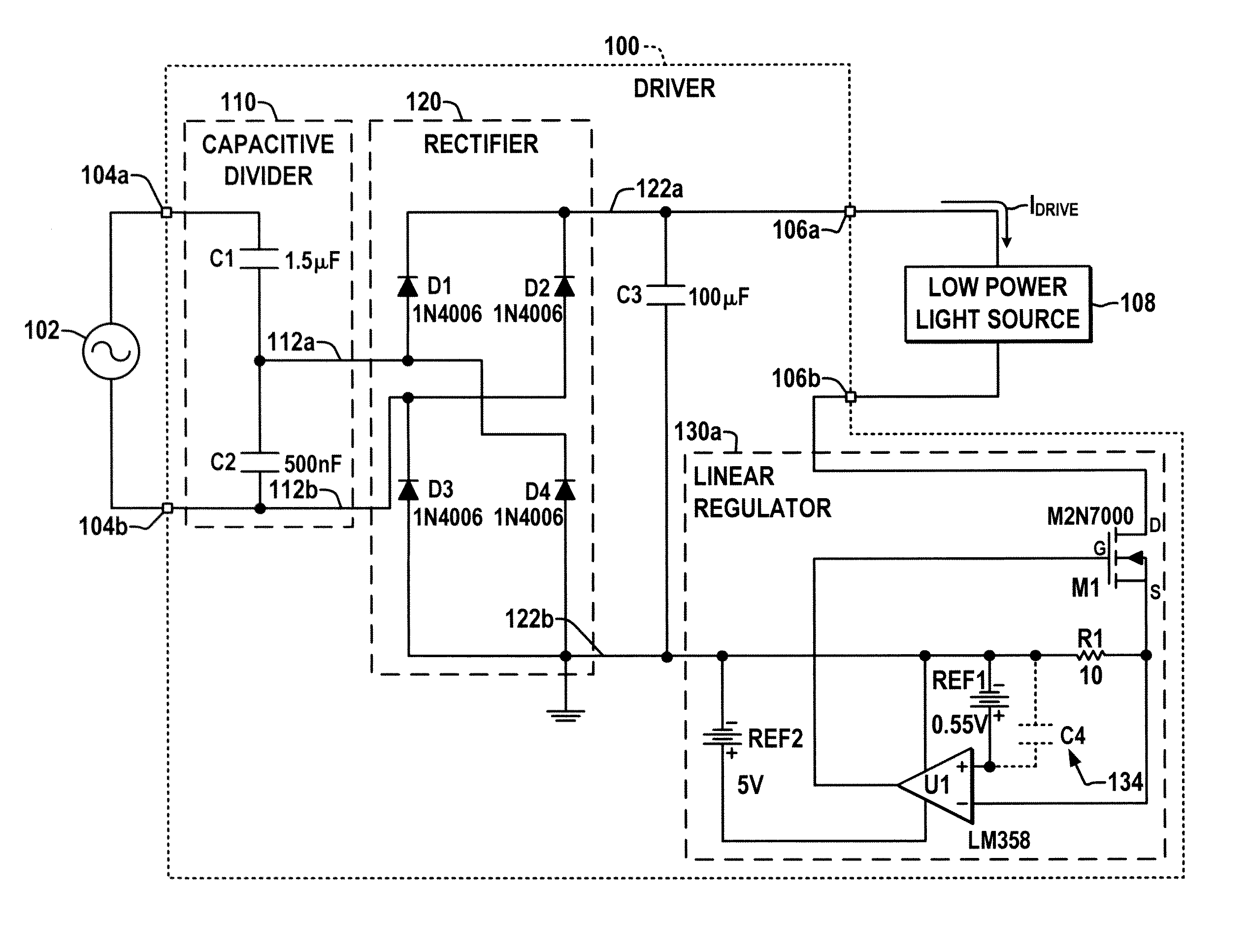
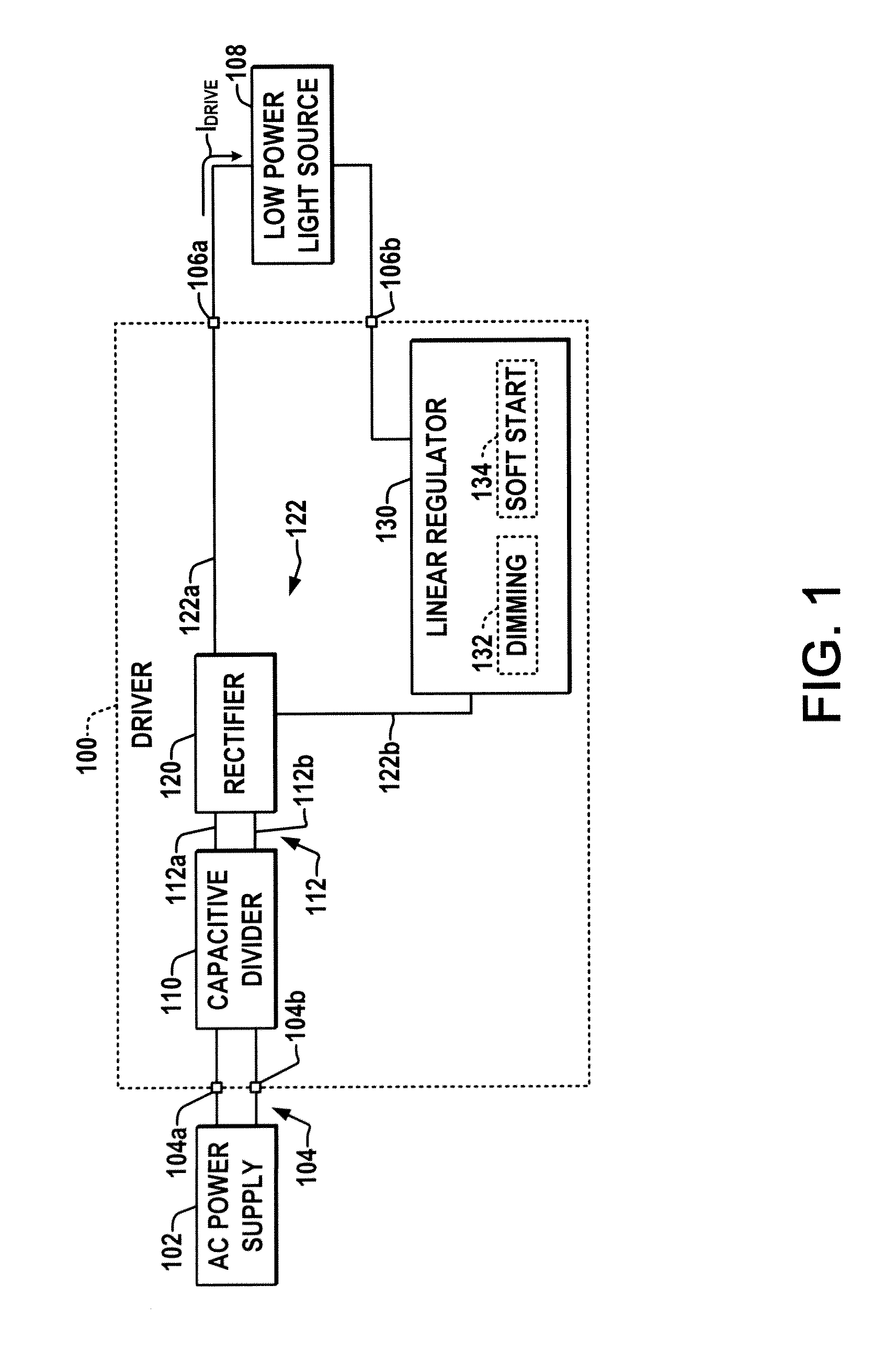
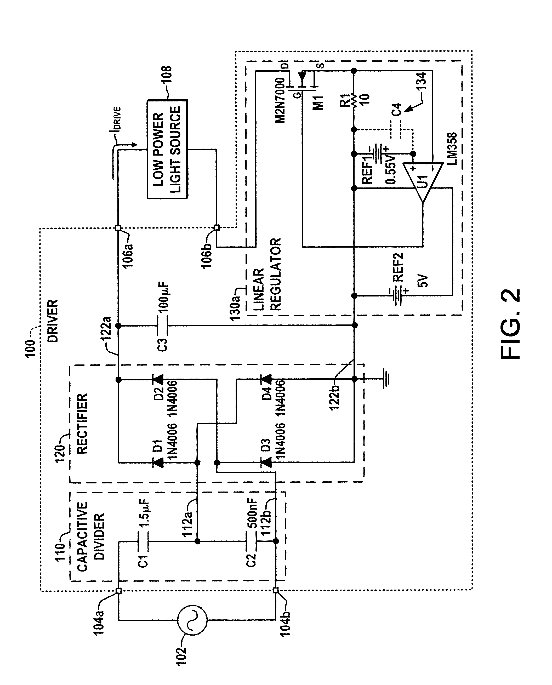
[0014]Referring now to the drawings, where like reference numerals are used to refer to like elements throughout, and where the various features are not necessarily drawn to scale, FIGS. 1-3 illustrate embodiments of a high efficiency, low power AC line voltage to DC driver apparatus 100 for powering one or more lighting devices 108, such as LEDs, OLEDS, etc. The driver 100 includes an input 104 with first and second input terminals 104a and 104b coupleable to a single or multi-phase AC power supply 102, such as a standard single-phase 120 VAC (RMS) power connection in the illustrated example (further input terminals, not shown, may be provided for multi-phase input connections). The input 104 is connected to a capacitive divider circuit 110 with first and second capacitances C1 and C2 (FIG. 2) coupled in a series branch between the terminals 104a and 104b to form a capacitive divider providing a reduced (divided) AC output at an intermediate node 112a. The first divider capacitance...


PUM


Abstract

A high efficiency low power DC driver apparatus is presented for powering a light source, with a capacitive divider circuit receiving an AC input and providing a divided AC output, a rectifier provide a DC output below ten watts, output terminals coupleable to one or more light sources, and a linear regulator coupled in series with the light source to regulate a drive current flowing through the series circuit.

Description

BACKGROUND OF THE DISCLOSURE[0001]This disclosure relates to low power DC lighting devices and DC driver apparatus. Low power DC lighting devices are becoming more and more popular. For example, light emitting diodes (LEDs) and organic LEDs (OLEDs) are gaining popularity in applications where single-digit wattage light output is desired. Driver circuits for powering such light sources from AC power supplies have thus far typically included multiple power conversion stages and have failed to provide good power efficiency. Attempts to improve efficiency by capacitor charging and a controlled half wave rectification have proven difficult to control. As a result, there is a need for improved low cost, low power, high efficiency drivers for converting AC input power to DC power as low power DC-driven lighting devices continue to proliferate.SUMMARY OF THE DISCLOSURE[0002]A high efficiency low power DC driver apparatus is provided for powering a light source. The driver apparatus has inpu...

Claims


Application Information

Patent Timeline
Patent Type & Authority Patents(United States)
IPC IPC(8): H05B37/00H05B44/00
CPCH02M7/06H05B33/0812H02M2001/0045Y02B20/343Y02B20/345H05B45/395Y02B20/30H02M1/0045H02M7/05Y02B20/40
Inventor ROBERTS, BRUCE RICHARDNERONE, LOUIS ROBERT
Owner SAVANT TECH LLC
Learn More