Dry tree semi-submersible platform for harsh environment and ultra deepwater applications

a technology for semi-submersible platforms and harsh environments, applied in the direction of moon-pools, special-purpose vessels, vessel construction, etc., can solve the problems of poor damping, poor damping, and low center of gravity of the entire semi-submerged vessel, so as to improve the fatigue life of the platform, increase structural stability, and reduce wave forces. the effect of significant reduction of wave forces

Inactive Publication Date: 2011-06-21
SRINIVASAN NAGAN
View PDF16 Cites 22 Cited by
  • Summary
  • Abstract
  • Description
  • Claims
  • Application Information

AI Technical Summary

Benefits of technology

[0014]A buoyant keel tank having a central moon pool is secured at the bottom ends of telescoping columns mounted in the main columns and can be retracted and extended relative to the main columns between a retracted transport mode and an extended operating mode. The weight and buoyancy of the main columns and keel tank is adjustably tuned to raise or lower the center of gravity of the entire mass of the structure with respect to its center of buoyancy according to ballast and variable or fixed loads including deck payloads, to stabilize the structure, and to compensate for different operational, environmental, survival and installation stages of the structure.
[0026]The structural and hydrodynamic response features of the present semi-submersible floating offshore platforms allow them to respond to effectively to heave motions and environmental forces in ultra-deepwater and the platform deck is independent of vertical riser and mooring loads, making them suitable for dry tree support in either low or moderate sea states as well as in extreme sea states.

Problems solved by technology

The center of gravity of the entire semi-submersible vessel is generally high due to large deck loads above the water.
Other problems with conventional semi-submersible platforms is that they are not well suited for dry tree support because their heave oscillation varies from a small magnitude in calm sea or small wave conditions to large in stormy rough sea or high wave conditions, the added mass and ballast mass of the pontoon is too large to effectively shift the natural period away from the calm wave period, and damping is very poor and predominantly radial in nature.
Thus, the moment connection at the bottom between the columns and the pontoon are subjected to these wave forces and the connection is also subjected to severe storm loadings and fatigue loadings.

Method used


Image

  • Dry tree semi-submersible platform for harsh environment and ultra deepwater applications
  • Dry tree semi-submersible platform for harsh environment and ultra deepwater applications
  • Dry tree semi-submersible platform for harsh environment and ultra deepwater applications

Examples


Embodiment Construction

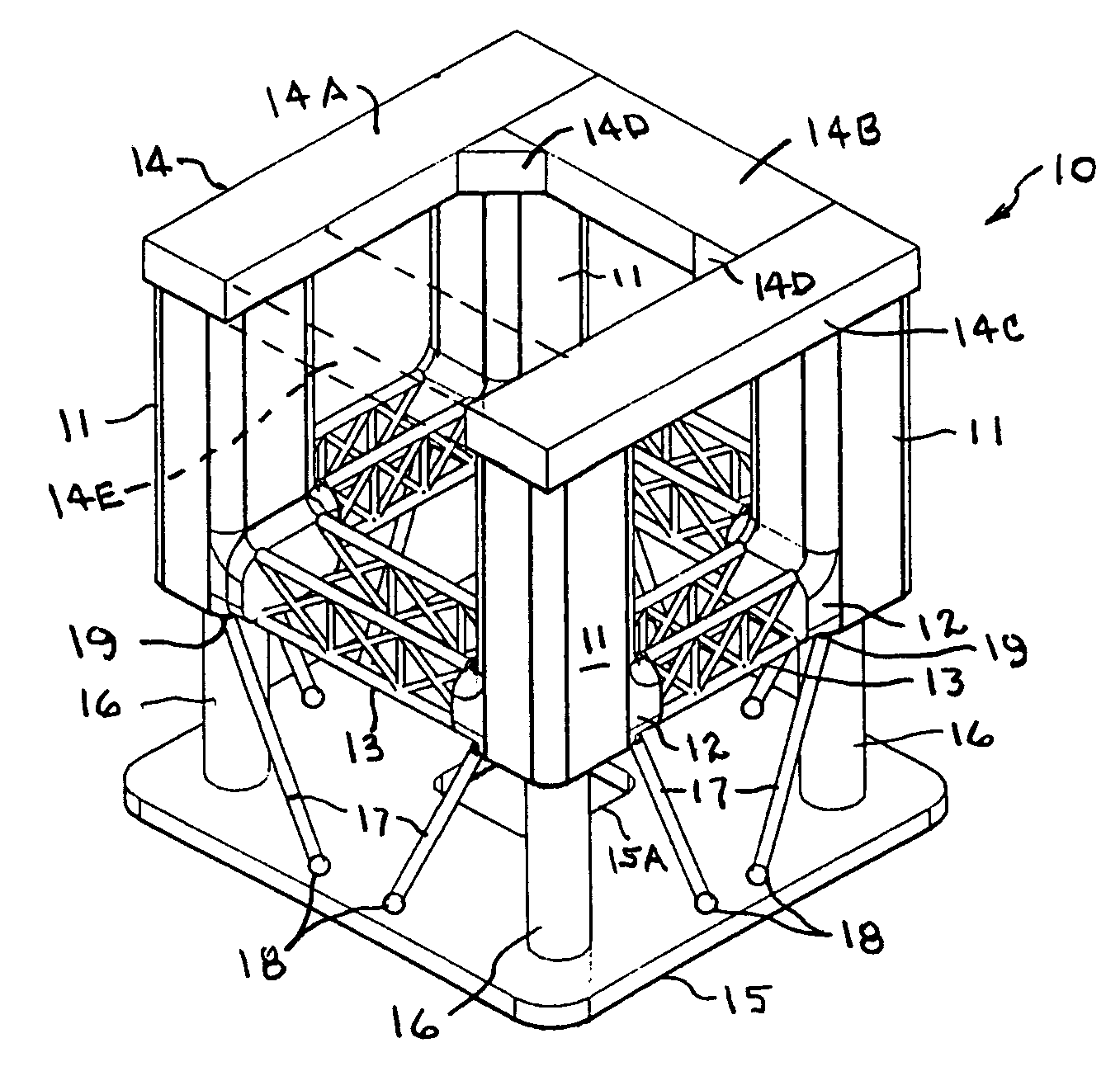
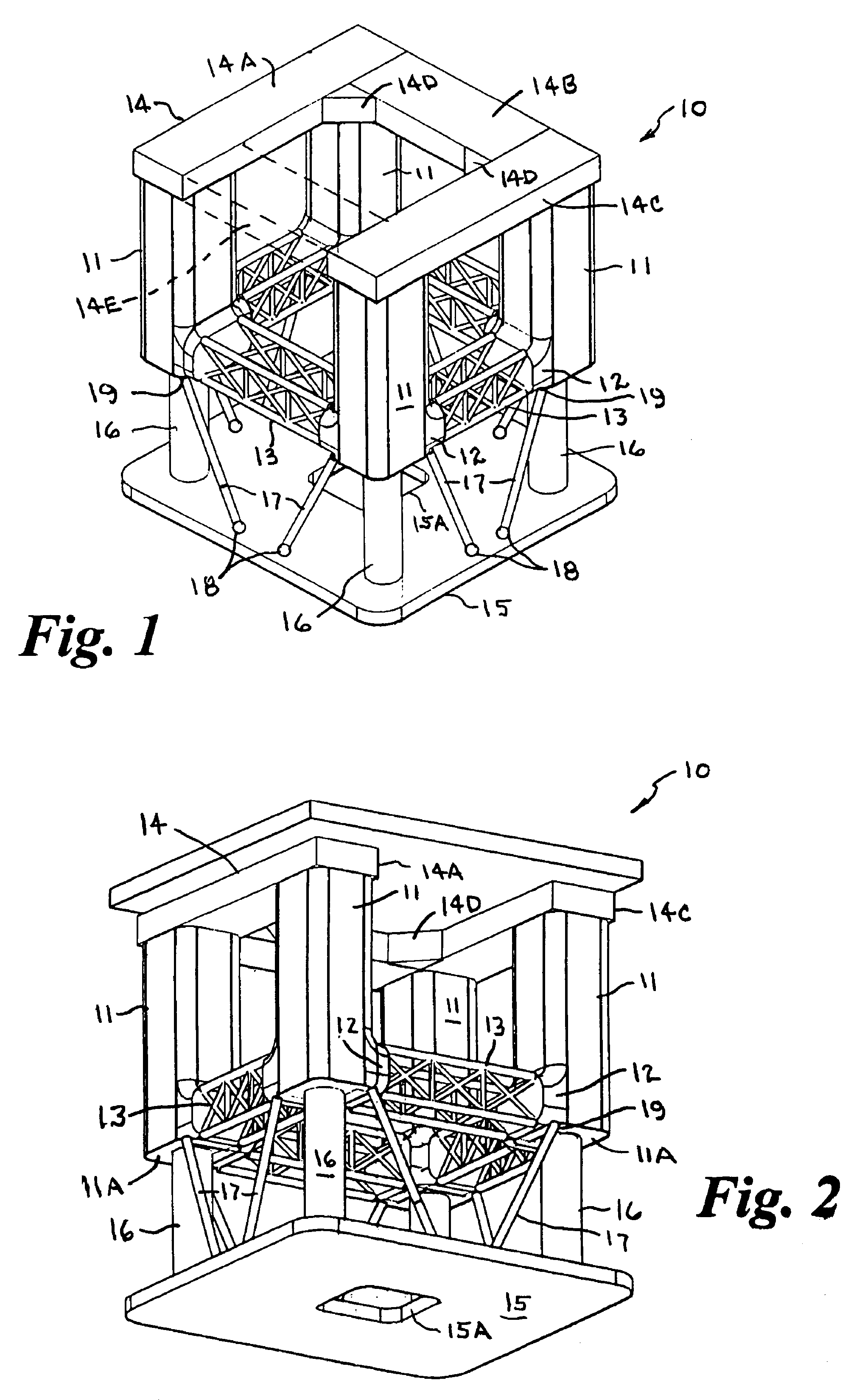
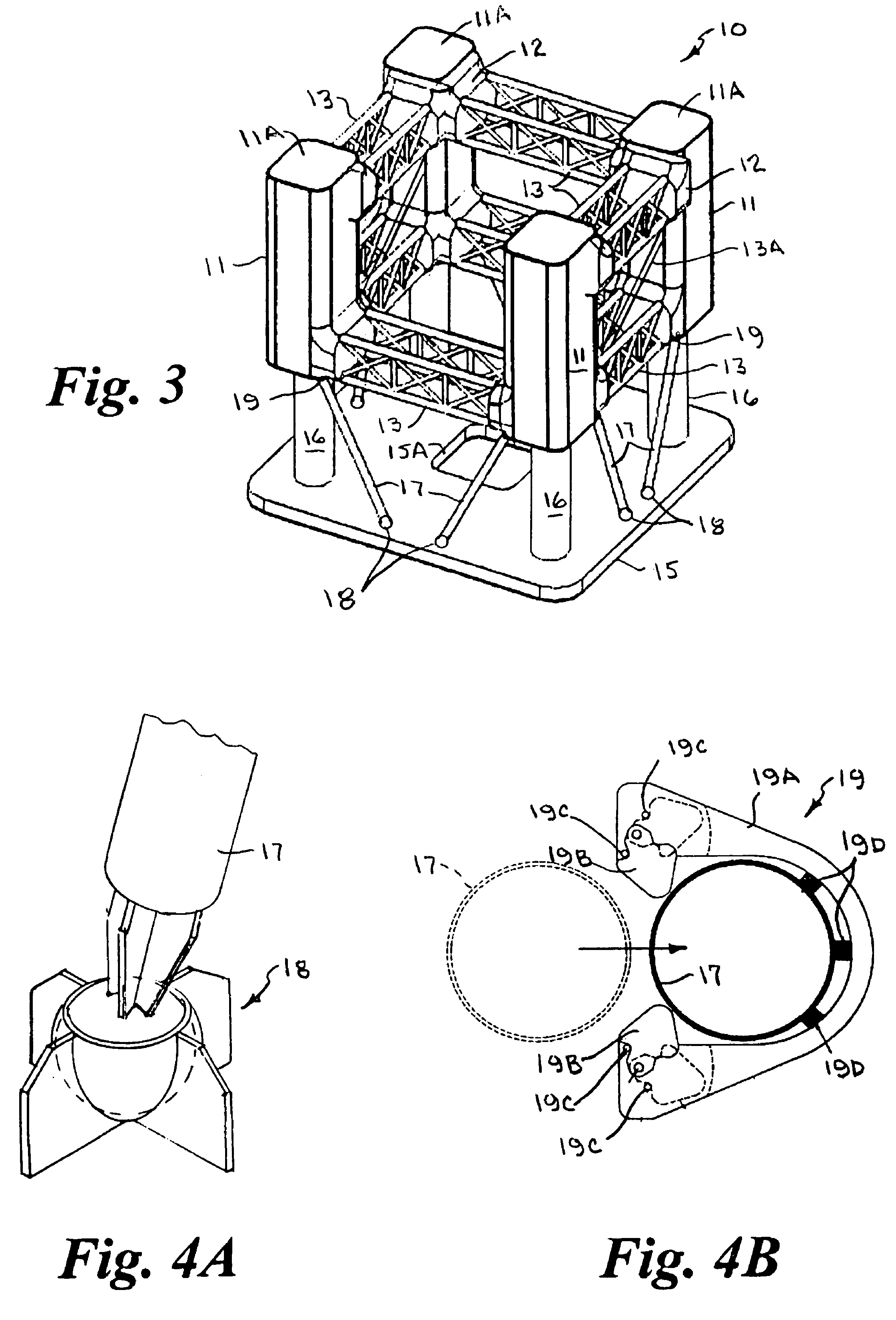
[0043]Referring now to FIGS. 1 and 2, there is shown, somewhat schematically, a column stabilized semi-submersible floating offshore drilling and production platform structure 10 in accordance with the present invention. The platform structure 10 has four main vertical columns 11, which may be of generally rectangular or circular cross section, with short horizontal lateral extensions 12 at their lower ends facing in opposed relation, and lateral truss members 13 formed of cross-braced tubular members extending horizontally between the extensions at the lower end of the main columns connecting the adjacent columns.

[0044]A generally C-shaped or U-shaped deck mount structure 14 is secured to the top ends of the main vertical columns 11 for receiving and supporting a deck D (seen in FIG. 2). The deck mount structure 14 has three box-like generally rectangular sides 14A, 14B and 14C formed of metal plate defining a hollow interior and is open on one side defining a wide opening between ...


PUM


Abstract

Column-stabilized floating offshore platform structures (10) having spaced apart buoyant main vertical columns (11) joined at lower ends by horizontal lower truss members (13) in a pin connection and joined at upper ends by a buoyant deck mount structure (14), and / or by horizontal truss members, to form a moment connection. A buoyant keel tank (15) having a central moon pool (15A) can be retracted and extended relative to the main columns between a retracted transport mode and an extended operating mode. Ballast of the columns and keel tank can be adjusted to raise or lower the center of gravity of the structure with respect to its center of buoyancy to stabilize the structure and compensate for variable or fixed loads, deck payloads, environmental conditions, and operational and installation stages. A three-sided deck mount allows on-site float-over deck installation.

Description

CROSS REFERENCE TO RELATED APPLICATION[0001]This application claims priority of U.S. Provisional Application Ser. No. 61 / 029,565, filed Feb. 19, 2008.BACKGROUND OF THE INVENTION[0002]1. Field of the Invention[0003]This invention relates generally to offshore floating vessels and platform structures used in the exploration and production of oil and gas products, and more particularly to an offshore floating platform structure having vertical columns connected at a lower end by lateral trusses, a telescoping keel tank supported beneath the columns, and a rectangular ring-like deck mount structure or a three-sided deck mount structure at the top of the columns open on one side to allow on-site float-over deck installation.[0004]2. Brief Description of the Prior Art[0005]In the following discussion the term “truss”, as used herein, refers to a welded or bolted cross braced open frame structure formed of slender tubular members. A truss bridges between vertical column structures to stabi...

Claims


Application Information

Patent Timeline
Patent Type & Authority Patents(United States)
IPC IPC(8): B63B35/44
CPCB63B9/065B63B39/00B63B35/44B63B1/107B63B35/4413B63B2003/147B63B77/00
Inventor SRINIVASAN, NAGAN
Owner SRINIVASAN NAGAN
Why Eureka
Try Eureka