
Thermal module assembly

a technology of thermal modules and modules, applied in the direction of light and heating equipment, semiconductor devices of light sources, laminated elements, etc., can solve the problems of increasing manufacturing inconvenience, unexpected deformation or loosening, and generating unexpected loosening, so as to improve the overall performance of heat dissipation, save manufacturing costs, and improve electrical insulation performance.

Inactive Publication Date: 2011-06-21
ABLECOM TECH
View PDF2 Cites 2 Cited by
  • Summary
  • Abstract
  • Description
  • Claims
  • Application Information

AI Technical Summary

Benefits of technology

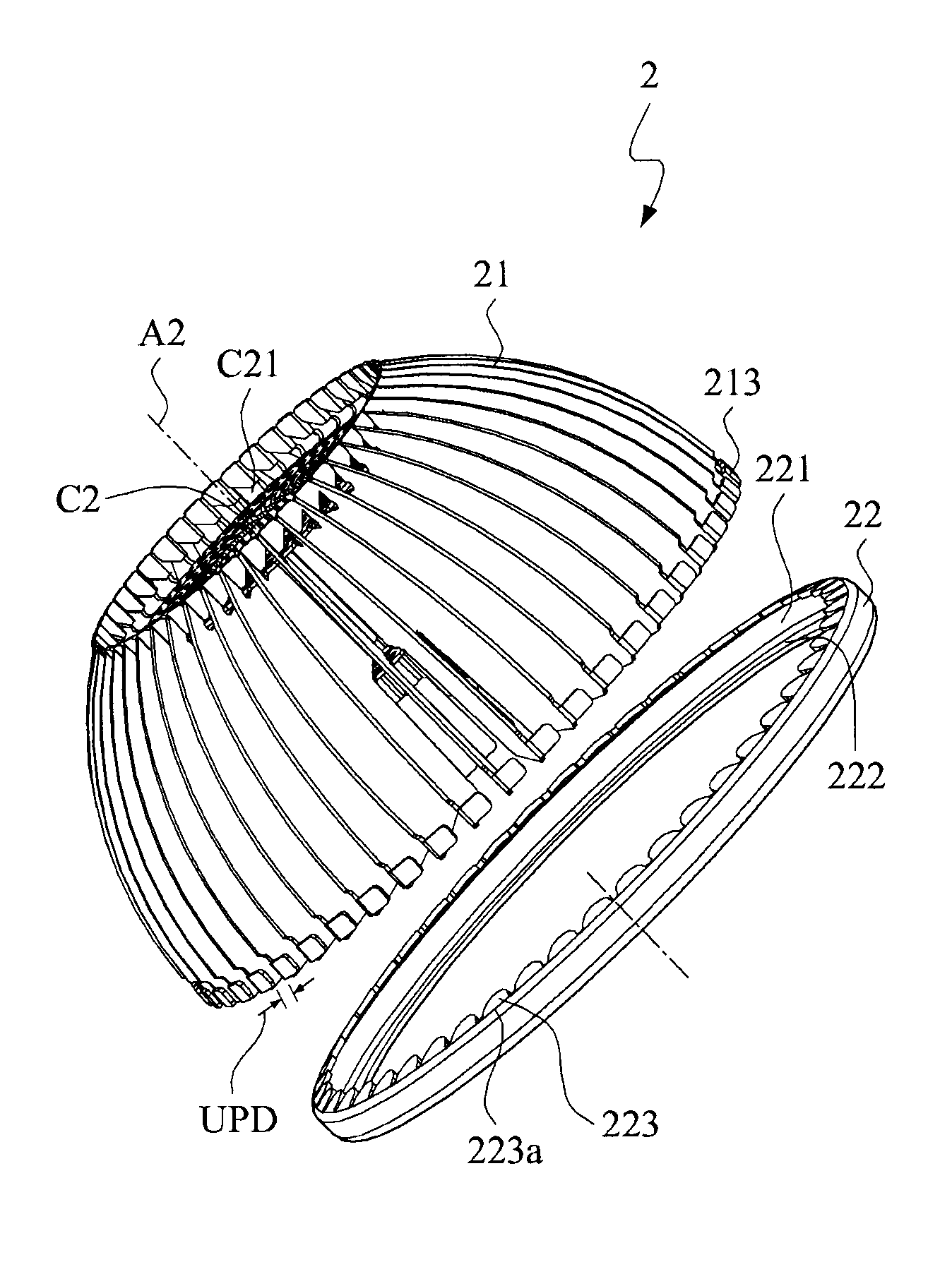
[0013]Thus, the primary objective of the present invention provides a thermal module assembly, in which a plurality of positioning folded plates are separately formed on an inner ring edge of a fixing ring to directly fix the heat dissipating fins and keep any two neighboring two of the heat dissipating fins in a unit pitch distance, so as to raise the arrangement symmetry of heat dissipating fins, and further to improve the performance of homogeneous heat conduction or heat dissipating and simplify the manufacturing processes.
[0014]The secondary objective of the present invention provides a thermal module assembly, in which a plurality of positioning folded plates are separately formed on an inner ring edge of a fixing ring to directly fix the heat dissipating fins. Therefore, it is not necessary to apply the compressive forces as mentioned, the heat dissipating fins and the fixing ring can be made of the same material, execute the anodic treatment or the antirust treatment together, so as to further simplify the manufacturing processes and keep well assembling conditions between the heat dissipating fins and the fixing ring.
[0016]In the preferred embodiment of the present invention, the heat dissipating fins and the fixing ring are made of aluminum alloy; therefore after the fixing ring hitches the heat dissipating the outer side of the heat dissipating fins, it is able to simultaneously execute the anodic treatment or the antirust treatment to the heat dissipating fins and the fixing ring to generate the anodic treatment layer or the antirust treatment layer, so as to provide well performance of electrical insulation and antirust. Meanwhile, after executing the anodic treatment or the antirust treatment, it is able to keep well assembling conditions between the heat dissipating fins and the fixing ring without unexpected deformation or loosening.
[0017]Form above description, comparing with the prior arts, in the present invention, a plurality of positioning folded plates are separately formed on the inner ring edge of the fixing ring; thus, it is able to directly fix the heat dissipating fins via the positioning folded plates, and keep any neighboring two of the heat dissipating plates keeping in the same unit pitch distance, so as to raise the homogeneity of heat conduction to improve the overall performance of heat dissipating, and further to save the cost of manufacturing.
[0018]Nevertheless, due to above reasons, the heat dissipating fins and the fixing ring can be made of the same material, and be treated via the anodic treatment or antirust treatment together to simplify the manufacturing processes. Thus, it is able to keep well connection conditions between the heat dissipating fins and the fixing ring to further save the cost of manufacturing and raise the yield rate of assembling the thermal module assembly. Additionally, due to above reasons, it is also to keep the smoothness of the appearance of the fixing without generating any recessed structures, and the heat dissipating fins and the fixing ring can be provided with the same color, so that the appearance workmanship of the thermal module assembly can be further improved.

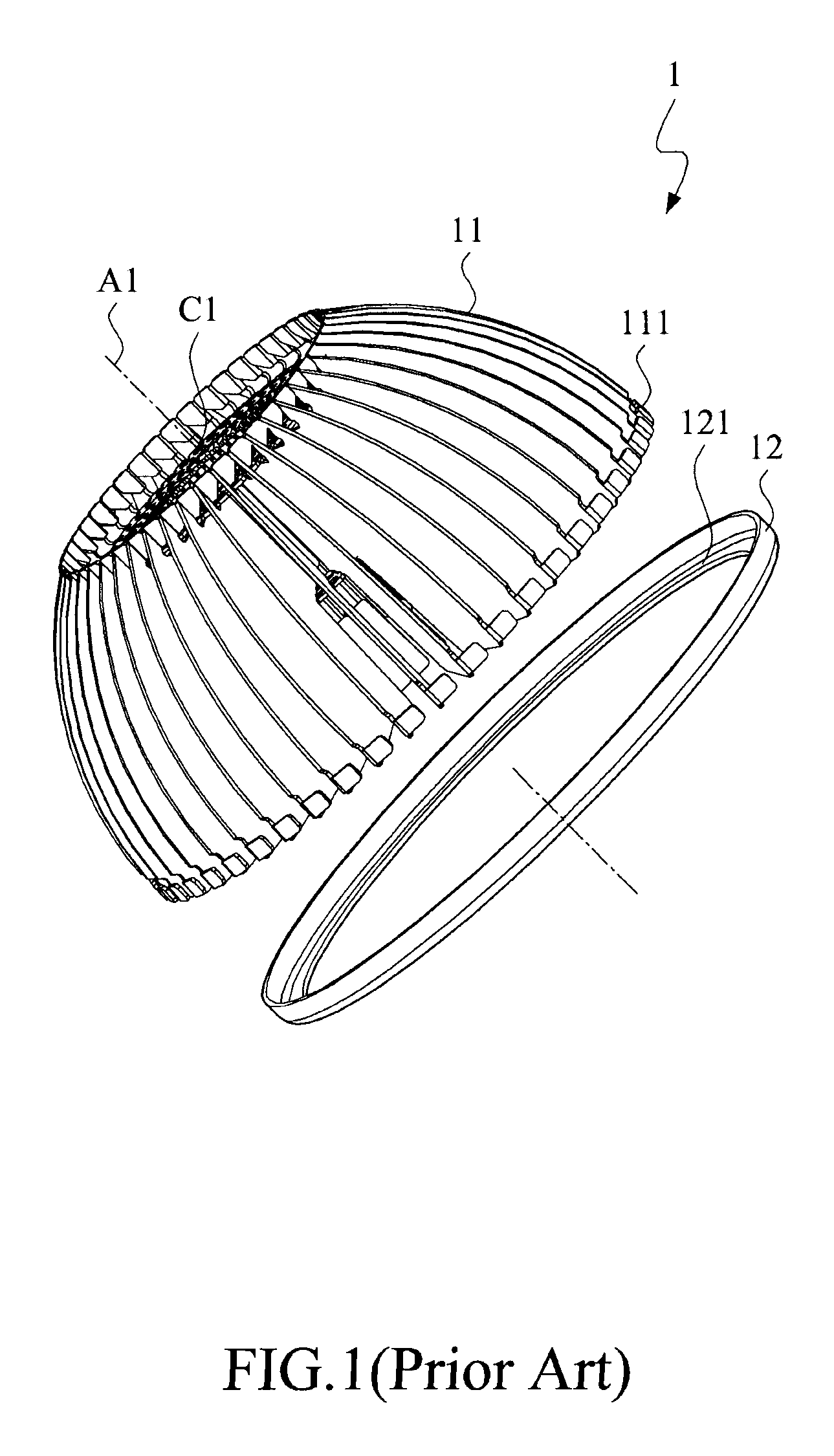
Problems solved by technology

First, it increases the inconvenience of manufacturing.
Third, if the gap between any neighboring two of the heat dissipating fins is too narrow or too wide, the unexpected deformation or the unexpected loosening will be generated.

Method used


Image

  • Thermal module assembly
  • Thermal module assembly
  • Thermal module assembly

Examples


Embodiment Construction

[0031]The technology of manufacturing the thermal module assembly as provided in accordance with the present invention can be widely use for manufacturing many kinds of thermal module assemblies of different illumination devices, the combined applications are too numerous to be enumerated and described, so that only one preferred embodiment capable of being positioned by two different positioning gauges is disclosed as follows for representation.

[0032]Please refer to FIG. 4 to FIG. 8, wherein FIG. 4 illustrates the structure of a heat dissipating fin; FIG. 5 illustrates thermal module assembly comprising a plurality of heat dissipating fins and a fixing ring in a preferred embodiment of the present invention; FIG. 6 illustrates the heat dissipating fins are arranged around a central axis in a ring-distributed position, and being hitched, positioned and fixed by a fixing ring in the preferred embodiment of the present invention; FIG. 7 illustrates the thermal module assembly is appli...


PUM


Abstract

A thermal module assembly is applied to dissipate heat energy released from a lighting assembly when working, and comprises a plurality of heat-dissipating fins being chain-connected and a fixing ring. The heat-dissipating fins are radially extended from a central region, and each heat-dissipating fin comprises a fin body, a chain-connected mechanism and an extended folded plate. The chain-connected mechanism is located on an inner side of the fin body for chain-connecting the neighbor heat-dissipating fin, and the extended folded plate is located on an outer side of the fin body. The fixing ring hitches the outer side of each heat-dissipating fin, and the fixing ring is formed with a plurality of positioning folded plates along an inner ring edge thereof, so as to fix the extended folded plate and keep any two neighboring heat-dissipating fins in a unit pitch distance.

Description

FIELD OF THE INVENTION[0001]The present invention relates to a thermal module assembly, and more particularly to a thermal module assembly for dissipating heat energy released from a lighting assembly, wherein a plurality of positioning folded plate is applied to fix the heat dissipating fins and keep any neighboring two of the heat dissipating fins in a unit pitch distance.BACKGROUND OF THE INVENTION[0002]For the present illumination devices, they are usually assembled with a lighting assembly to project at least one illumination light beam to provide the function of illumination. In practice, the light emitting diodes (LEDs) can provide the performances of high power, high illumination, low power consumption and long life of use, so that the LEDs are usually applied to manufacture the illumination devices.[0003]Actually, the LEDs also release heat energy when projecting illumination light beams to external environment. In the most conditions, if the heat energy can not be effectiv...

Claims


Application Information

Patent Timeline
Patent Type & Authority Patents(United States)
IPC IPC(8): F21V29/00H05K7/20
CPCF21V29/004F21V29/89F21V29/773F21Y2101/02F28F3/02F21Y2115/10
Inventor LIANG, CHIEN-KUO
Owner ABLECOM TECH
Learn More