
Hand accessory

a technology for hand accessories and hand pads, applied in golfing accessories, protective garments, gymnastics, etc., can solve the problems of increased stress on the upper hand, increased stress on the weaker upper hand, and discomfort in the gripping process, so as to avoid stress or impingement on the thumb muscle, improve gripping effect, and improve gripping

Inactive Publication Date: 2011-06-21
FROST JOHN H
View PDF11 Cites 12 Cited by
  • Summary
  • Abstract
  • Description
  • Claims
  • Application Information

AI Technical Summary

Benefits of technology

The solution effectively channels force to the lower hand's tougher areas, reducing stress on the upper hand, providing better thumb protection, and allowing for optimal grip strength and control throughout the gripping and swinging phases, including phase two where the hand moves fully into a lower and outward position.

Problems solved by technology

The inventor's prior two patents explained the problem of bulkiness in the upper hand / web area: although many forms of padding may serve to protect the thumb from bruising, the bulkiness created by the padding also receives and creates more stress in the weaker upper hand as well as discomfort in the gripping process.
Embodiment 400, used in games by some professional baseball players, was difficult to improve upon.
It provided adequate thumb joint protection and had perfect comfort and bat control in the initial gripping position (phase one) and good control in the ending position (phase three / four), but did not conform perfectly to the hand's “tuck” movement in phase two, and was not widely accepted for bottom hand usage.
An ongoing problem has been bulkiness in the web area not only adding stress to the upper hand at the wrist, but also impinging on the middle and index finger tendons as the thumb base moves downward, as well as stress on the thumb's second joint, third joint (carpal area) and thumb base muscles.
However, neither 203 nor 300 provided adequate protection of the thumb from bruising.
Another problem with previous embodiments was stabilizing the primary contact area 506 against the inertial force of a bat being swung (hand parallel to the ground, bottom of the hand leading), forcing the hand accessory upwards in the hand.
At the end of phase three, there is little space left for any hand accessory material, which creates a challenge in finding a means of insulating the thumb from bruising.

Method used


Image

  • Hand accessory
  • Hand accessory
  • Hand accessory

Examples


embodiment 400

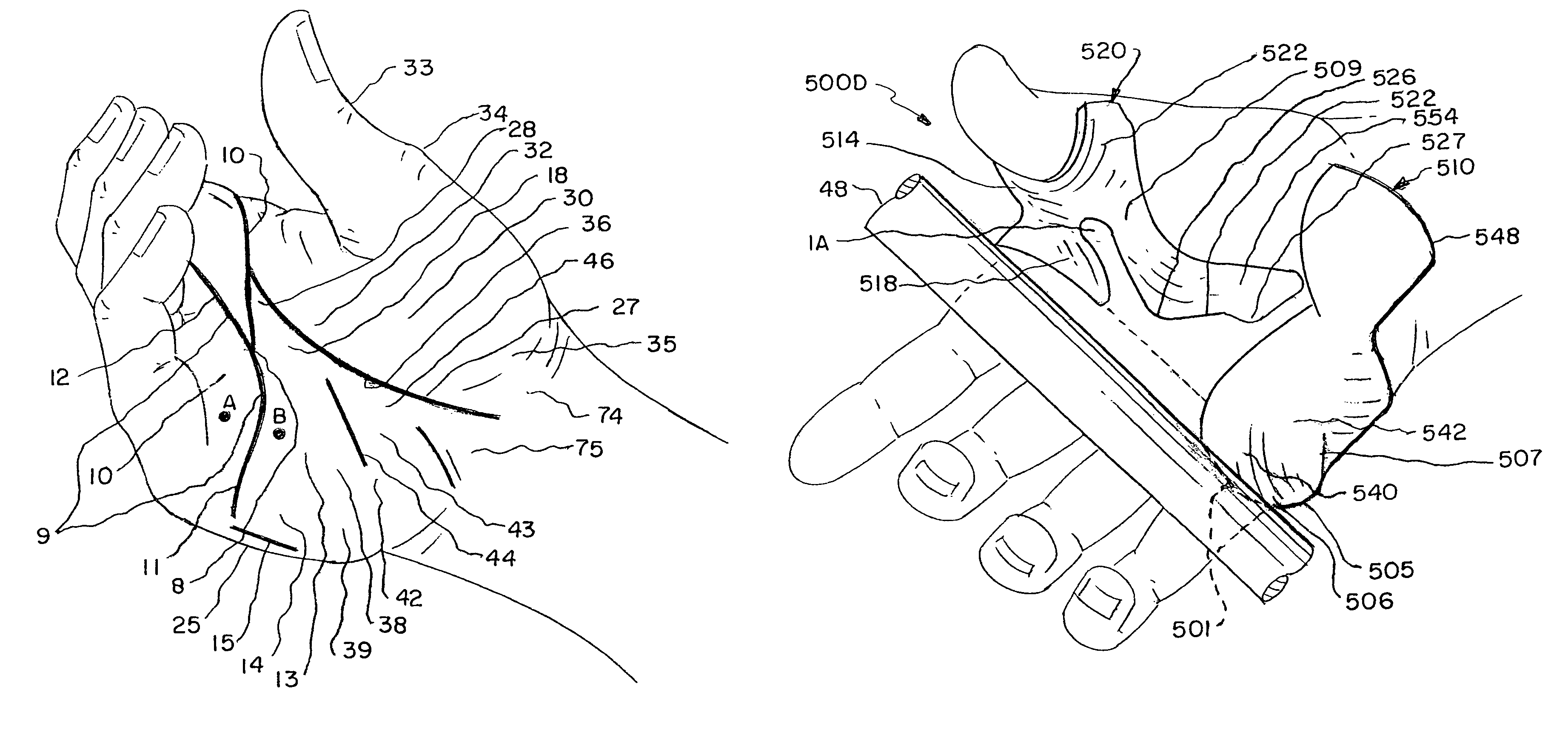
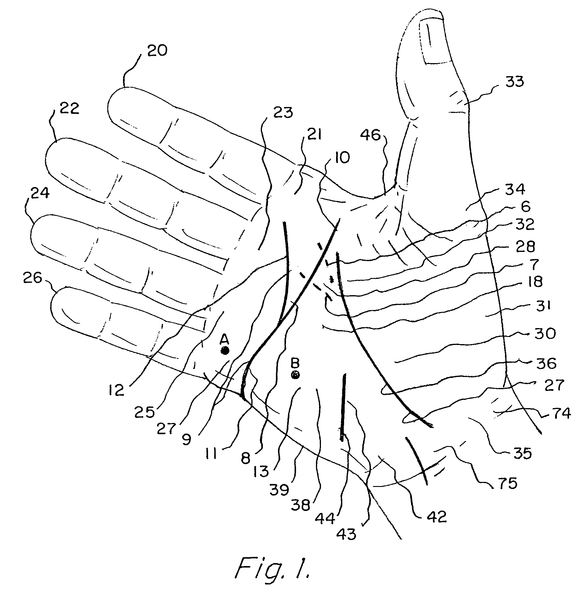
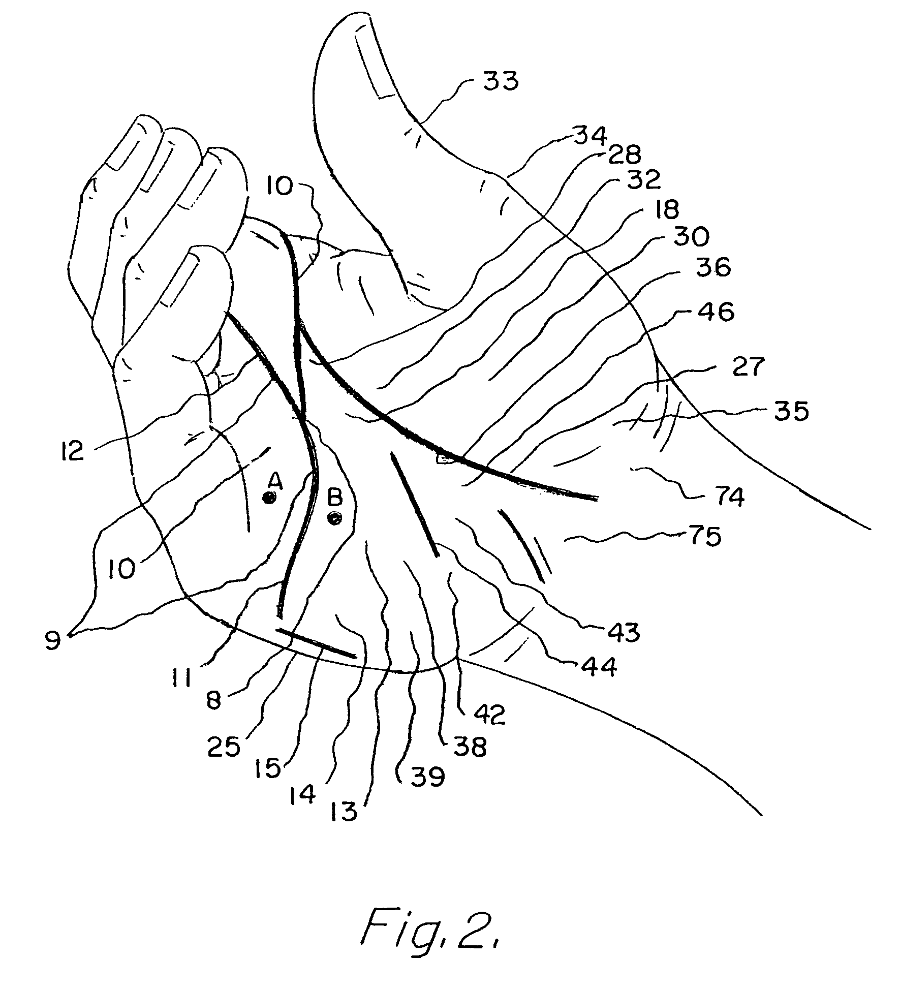
[0050]There is an area within the hand which acts as a fault line, allowing portions on either side to move in opposite directions (like a loose hinge). In embodiment 400 the line was referred to as a transverse crease running from the inside of the little finger knuckle 27 upward to the top of the hand. This area is important in understanding the gripping motion and will be further named and analyzed as follows: Lower transverse crease 11 extends from the inside of little finger knuckle 27 at the bottom of the hand to ring finger hollow 8, thence becoming outer transverse crease 12 branching (as a “Y”) to intersect middle finger 22 and index finger 20. That area acts like a fault line, being the greatest area of movement or “shifting” during phase two of the grip. The portion extending from ring finger hollow 8 upward to the inside of index finger knuckle 21 bordering upper web 46 being upper transverse crease 10. The “fault line” area, the line extending from the base of lower tra...

embodiment 500b

[0059 seen in FIGS. 5 & 6 describes by comparison, a much wider and encompassing thumb harness 554 extending to somewhat overlap thumb buffer 548 during certain phases of the grip, (FIG. 6), then angles outwardly to junction 530 such that the inner hand space 5 of 500A is now reduced to upper space 2 and lower space 3.

[0060]The phase two relocation channel 570 of 500B is deepened further, not only by the extension of handle wedge 505, but by bridge 540 and primary contact area 506 arcing further externally and downwardly creating handle space 512 below the hand's lower tough ball and also conforming with little knuckle phase two position.

[0061]Thus, 500B upper hand grip 520 and lower hand grip 510 are similar to embodiment 500A, however the two anchors are joined by a thin, narrow swivel 515 of basically no length, swivel 515 being the uppermost portion of junction 530. The upper and outermost portion of junction 530 presses into ring finger hollow 8 as ring finger fulcrum 541, then...


PUM


Abstract

A hand accessory designed to harness power from strong areas of the hand and channel stress away from weaker areas by means of anchors pressing into tough fleshy areas with connecting structure capable of leveraging a handle away from sensitive bony areas, relocating fleshy areas into supporting and insulating positions, preventing bone bruises and widening the effective grip of the hand for greater control while augmenting the hand's range of motion especially in swinging a baseball bat.

Description

BACKGROUND OF THE INVENTION[0001]1. Field of the Invention[0002]The field of this invention relates generally to hand accessories useful for improving the control and gripping strength of the hand in connection with the handle of an implement, such as a baseball bat, thereby reducing stress to the hand and providing greater control of the handle. More specifically, the current invention distributes force from a recoiling or heavy handle in varying degrees to various areas of the hand in accordance with the suitability of those areas in absorbing force, and / or transferring force to a handle, thus stronger areas of the hand are utilized than would be possible without the invention.[0003]2. Description of the Prior Art[0004]The subject matter of the present invention is an improvement over the structure defined within U.S. Pat. No. 7,179,180 B1 filed Apr. 26, 2005 and U.S. Pat. No. 7,431,671 filed Mar. 10, 2006, invented by the present inventor and designed to enhance the user's grippi...

Claims


Application Information

Patent Timeline
Patent Type & Authority Patents(United States)
IPC IPC(8): A63B69/00
CPCA63B23/16A63B21/4017A63B2069/0008
Inventor FROST, JOHN H.
Owner FROST JOHN H
Learn More