High magnification compact zoom lens

a compact, zoom lens technology, applied in the field of compact zoom lenses, can solve the problems of image blur increased power consumption required to move the fourth lens group for focusing, etc., to achieve the effect of reducing the weight, reducing the magnification ratio, and reducing the weight of the integrated image stabilizer or the vibration compensating mechanism

Inactive Publication Date: 2011-06-21
TAMRON
View PDF7 Cites 7 Cited by
  • Summary
  • Abstract
  • Description
  • Claims
  • Application Information

AI Technical Summary

Benefits of technology

[0046]In the high magnification compact zoom lens according to the present invention, the groups of lens pieces closer to the imaging plane are reduced in diameter to have the resultant zoom lens downsized and reduced in weight, retaining a magnification as high as 20 diameters, and the integrated image stabilizer or the vibration compensating mechanism is also reduced in dimensions.
[0047]Also in the high magnification compact zoom lens according to the present invention, the closest focusing distance at the telephoto end is ten times as long as or even smaller than the focal length at the telephoto end.
[0048]Additionally, in the high magnification compact zoom lens according to the present invention, one or more of the lens pieces in any lens group closer to the imaging plane has an aspherical surface on at least one of the opposite sides thereof so as to satisfactorily compensate for the chromatic aberration and the aspherical aberration.
[0049]In the high magnification wide-view zoom lens according to the present invention, various types of aberration are corrected well, and the resultant zoom lens is enhanced in magnification as high as 20 diameters and has a field of view of 75 degrees or even wider at the wide-angle end.
[0050]In the wide-view anti-vibration zoom lens according to the present invention, magnification ratios can be raised as high as those enabled in cameras that employ imaging devices, and image blur resulted from tremors of the hand(s) and / or other vibrations can be optically corrected. In addition, well-balanced compensation for various types of aberration can be guaranteed throughout the zoom range, and the anti-vibration lens subset reduced in diameter necessitates a reduced power to actuate them.

Problems solved by technology

Typically, with lens optics of high zoom ratio, an image obtained at the telephoto end is reduced in angle of field and increased in magnification, which results in minute tremors of the hand(s) causing the image to blur.
An additional problem is that, in order to shorten the focusing distance or the minimum working distance from the subject to the zoom lens at its telephoto end, the fourth lens group should accordingly have the greater effective diameter, resulting in increased power consumption required to move the fourth lens group for the focusing.
An additional problem is that, in order to shorten the focusing distance of the zoom lens at its telephoto end, the fourth lens group should have a greater effective diameter, resulting in increased power consumption required to move the fourth lens group for the focusing.
An additional problem is that, in order to shorten the closest focusing distance from the subject to the zoom lens at its telephoto end, the fourth lens group should accordingly have the greater effective diameter, resulting in increased power consumption required to move the fourth lens group for the focusing.

Method used


Image

  • High magnification compact zoom lens
  • High magnification compact zoom lens
  • High magnification compact zoom lens

Examples


embodiment 1

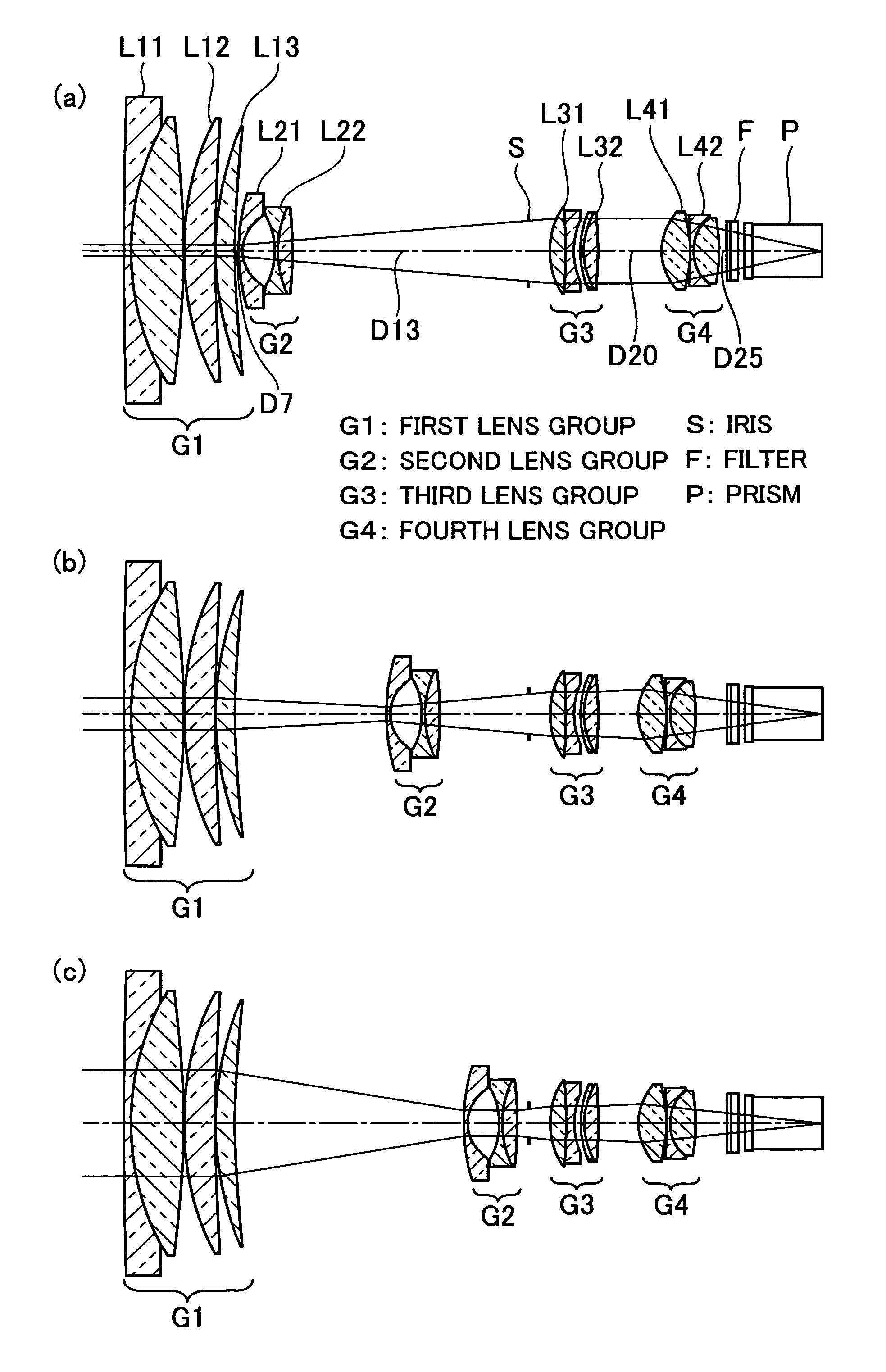
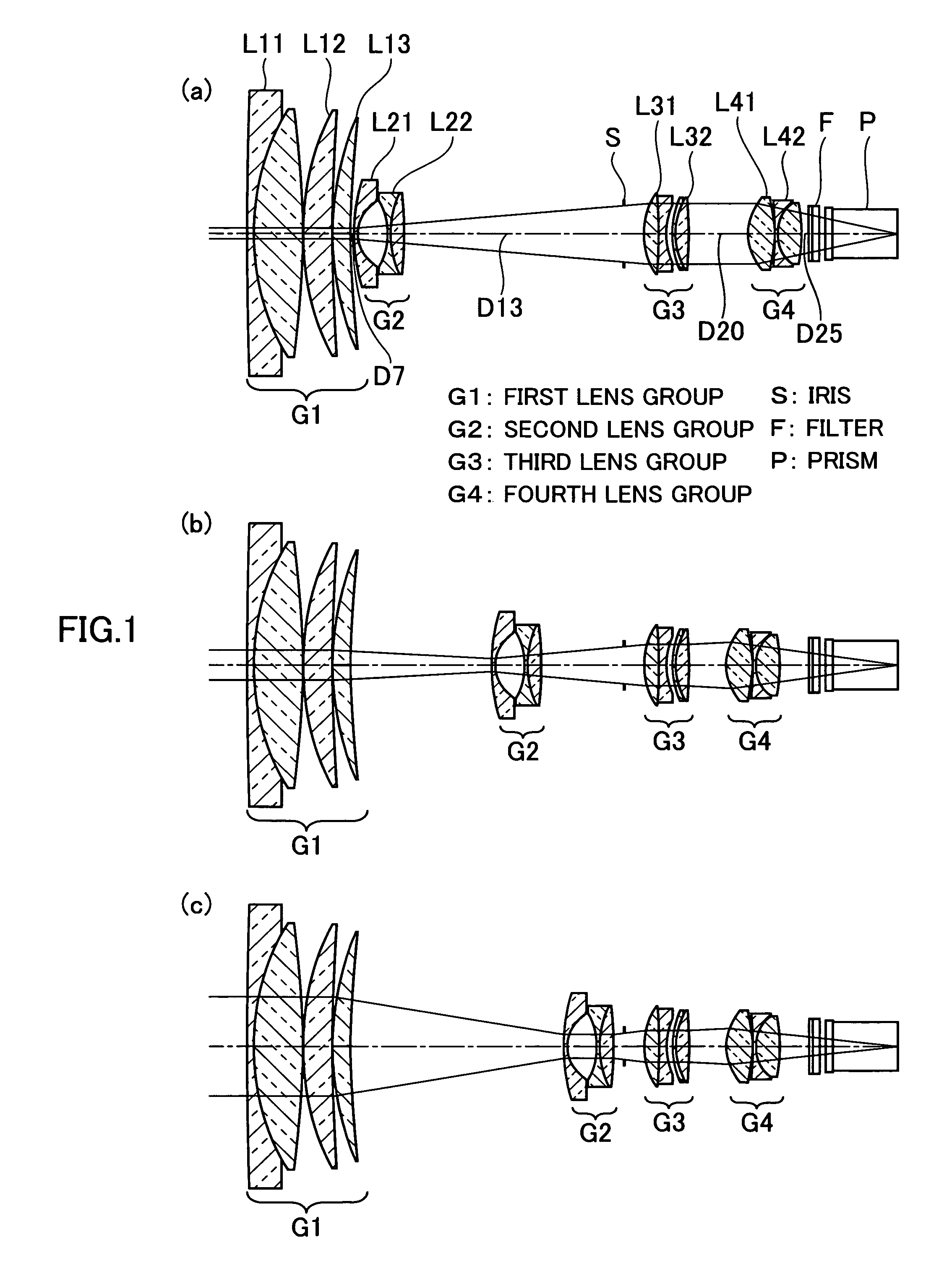
[0066]Table 1 below shows various numerical data on a first preferred embodiment of a wide-view anti-vibration zoom lens according to the present invention where all the values are scaled to a normalized minimum focal length of 1 millimeter (mm). In Table 1, S is a number of surfaces, ASPH designates an aspherical surface, R is a radius of curvature in millimeters (mm), D is a thickness or a distance in millimeters (mm), Nd is a refractive index of the d-line (λ=587.6 nm), and ABv is an Abbe constant in relation with the d-line.

[0067]Aspherical surfaces can be expressed as in the following formula (20):

[0068]z=y2R(1+1-(1+K)⁢y / R2)2+Ay4+By6+Cy8+Dy10(20)

where z is a depth of the aspherical surfaces, y is a height, R is a paraxial radius of curvature, K, A, B, C, and D denote a degree of asphericity, and the aspherical surfaces have their respective degrees of asphericity as listed in Table 1 below.

[0069]

TABLE 1SRDNdABv 1185.65560.40281.9036631.31 213.47782.83101.4970081.61 3−45.08820.0...

embodiment 2

[0077]Various numerical data on a second preferred embodiment of the wide-view anti-vibration zoom lens according to the present invention are listed in Table 2 similar to Table 1 where all the values are scaled to a normalized minimum focal length of 1 millimeter (mm).

[0078]

TABLE 2SRDNdABv 1187.95720.39101.9036631.31 214.50512.59791.4970081.61 3−43.71270.0355 414.68791.50341.7291654.67 584.13690.0355 616.23510.85691.8348142.72 732.0543(D7) 8 ASPH13.99320.04741.5361041.20 910.11020.18961.8830040.80102.15641.565811−3.29170.14221.8830040.8012−14.21800.03551325.70720.14221.9036631.31149.71560.66721.9459517.9815−9.7156(D15)Aperture0.00001.1848173.96270.70541.6668033.051872.37950.21331.8147437.0319 ASPH4.37890.4823208.97020.14221.8061033.27215.39910.70171.4874970.4422−14.5476(D22)23 ASPH3.42741.54031.6935053.3424 ASPH−8.88830.035525−19.96510.14221.8340037.34262.41711.12561.4970081.6127−7.6964(D27)280.00000.10191.5168064.20290.00000.46451.6180063.39300.00000.2915310.00000.40281.5168064.20...

embodiment 3

[0086]Various numerical data on a third preferred embodiment of the wide-view anti-vibration zoom lens according to the present invention are listed in Table 3 similar to Table 1 where all the values are scaled to a normalized minimum focal length of 1 millimeter (mm).

[0087]

TABLE 3SRDNdABV 1187.20380.40281.9036631.31 214.57352.59601.4970081.61 3−44.78670.0355 414.79861.54041.7291654.67 595.97160.0355 616.32700.85591.8348142.72 731.2796(D7) 8 ASPH17.67480.04741.5361041.20 911.75230.18961.8830040.80102.19341.531311−3.37430.14221.8830040.8012−14.21800.03551326.51080.14221.9036631.31149.66410.67031.9459517.9815−9.6641(D15)Aperture0.00001.184817 ASPH3.46090.78331.6889331.161844.08760.14221.8061033.27193.61800.5368208.03600.14221.8061033.27214.93640.71311.4874970.4422−15.98853.640223 ASPH3.38501.50061.6935053.3424 ASPH−8.87830.035525−20.02600.14221.8340037.34262.41711.16531.4970081.6127−7.7420(D27)280.00000.10191.5168064.20290.00000.46451.6180063.39300.00000.2915310.00000.40281.5168064.20...


PUM


Abstract

The present invention is directed to high magnification compact zoom lenses that are reduced in diameter of groups of lens pieces closer to the imaging plane to provide downsized lightweight zoom lenses of magnification as high as 20 diameters, with an image stabilizer or vibration compensating mechanism being also reduced in dimensions. An exemplary improved high magnification zoom lens has four groups of lens pieces, namely, the first or leading lens group G1 of positive refractivity in the foremost position closer to the subject, the second lens group G2 of negative refractivity, the third lens group G3 of positive refractivity, and the fourth lens group G4 of positive refractivity in the rearmost position closer to the imaging plane, all arranged in this order. In displacing the entire lens optics of the zoom lens from the wide-angle end to the telephoto end, the second lens group G2 are moved toward the imaging plane and the fourth lens group G4 are moved to compensate for a varied position of the resultant image while the first and third lens groups, G1 and G3, have their respective positions fixed along the optical axis. The zoom lens satisfies the requirements as defined in the following formulae: f3 / f4>2.0 and v4>65 where f3 is a focal length of the third lens group G3, f4 is the focal length of the fourth lens group, v4 is an average of Abbe contrasts of all the convex lens pieces in the fourth lens group G4.

Description

FIELD OF THE INVENTION[0001]The present invention relates to compact zoom lenses of magnification as high as 20 diameters that are suitable for optical apparatuses, such as video cameras, digital still cameras, and the like, having a plurality of imaging devices integrated therein.[0002]In general, cameras having an increased number of integrated imaging are required to correspondingly have a longer back focus, namely, a longer distance from the rearmost surface of the lens to the imaging plane. In one well known example of wide-view zoom lenses suitable for video cameras, digital still cameras, and the like that use an opto-electrical converter to opto-electrically convert rays reflected from the subject into signals, there are four groups of lens pieces arranged to exert their respective optical attributes of refractive power like positive-negative-positive-positive in this order.[0003]Typically, with lens optics of high zoom ratio, an image obtained at the telephoto end is reduce...

Claims


Application Information

Patent Timeline
Patent Type & Authority Patents(United States)
IPC IPC(8): G02B15/14
CPCG02B27/646G02B15/173G02B15/144113
Inventor LI, DAYONGNARA, TORU
Owner TAMRON
Why Eureka
Try Eureka