Grass-cutting head with spiral guide channels for the cutting line

a cutting line and spiral guide technology, applied in the field of cutting head, can solve the problems of frequent breakage of cutting line and considerable difficulties, and achieve the effect of facilitating line projection and reducing the tendency of line breakag

Active Publication Date: 2011-06-28
ARNETOLI MOTOR
View PDF39 Cites 19 Cited by
  • Summary
  • Abstract
  • Description
  • Claims
  • Application Information

AI Technical Summary

Benefits of technology

[0008]The object of the present invention is to produce a grass-cutting head which overcomes entirely or in part the aforesaid drawbacks and which in particular reduces the tendency of the line to break due to impact with obstructions surrounding the head during cutting and / or facilitates projection of the line, even if it breaks at the level of the outlet hole, or at the level of the outlet bushing from the body of the head.
[0011]In practice, the channel is produced in portions of the body of the head which project gradually with respect to a basic shape substantially with a circular section of said body and the line is fed from said projections with a non-radial orientation, but inclined with respect to a radial plane. In this way improved operation of the head is obtained, with regard to the consequences of impact with possible obstructions around the head during operation.

Problems solved by technology

In all conventional heads, including the head produced as indicated in U.S. Pat. No. 4,271,595, the cutting line is subject to frequent breakages due to high impact against any obstructions which may be present around the grass-cutting head (such as stones, clods of hard soil or the like) and also due to any particularly coarse vegetation present.
When this occurs, considerable difficulties can be encountered when passing a new portion of line required to continue with the cutting operation through the hole.
This conformation has the object of reducing strains and overheating of the line, but does not overcome the aforesaid drawbacks, related to retraction of the broken end of the line into the housing of the spool.

Method used


Image

  • Grass-cutting head with spiral guide channels for the cutting line
  • Grass-cutting head with spiral guide channels for the cutting line
  • Grass-cutting head with spiral guide channels for the cutting line

Examples


Embodiment Construction

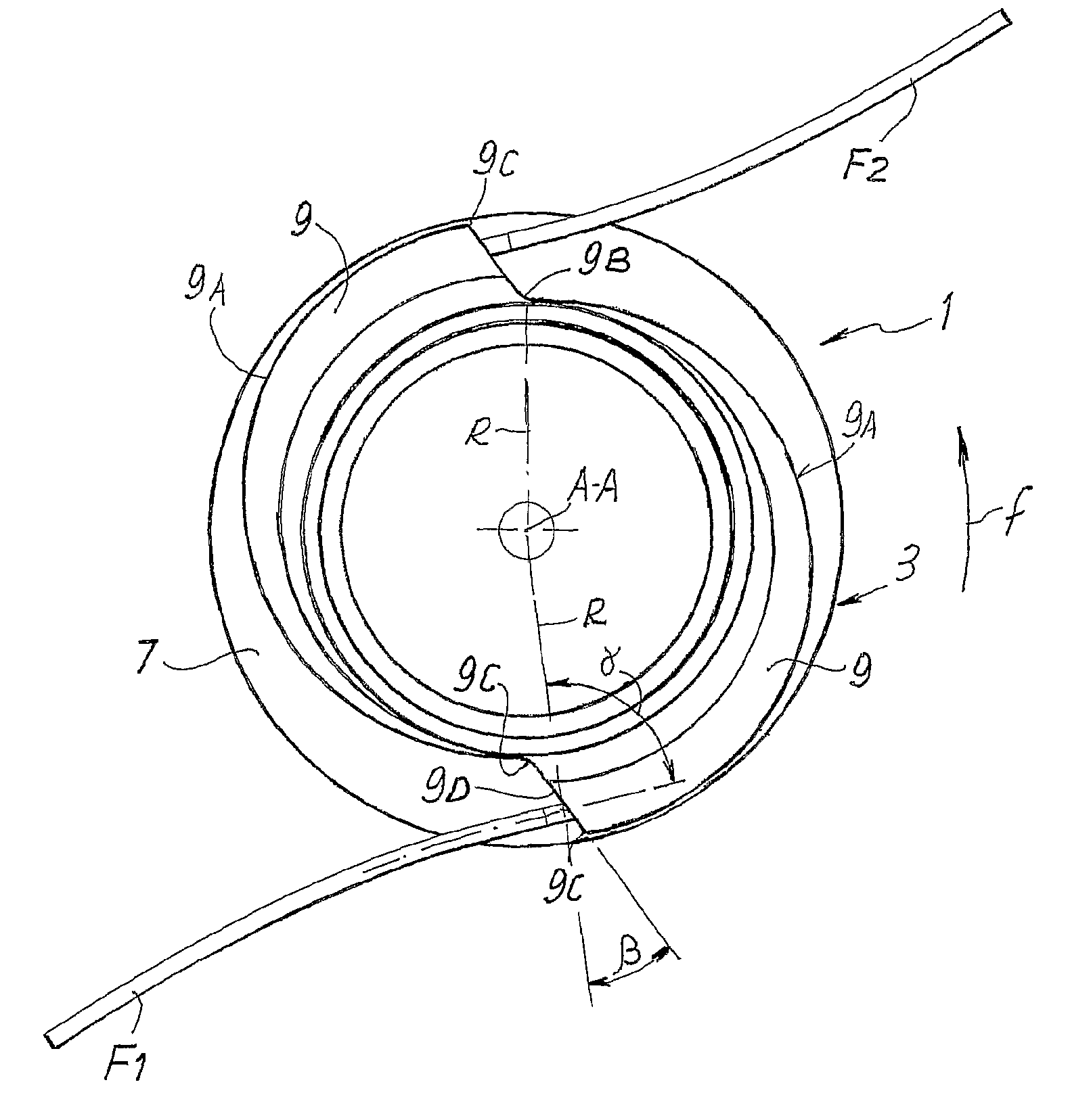
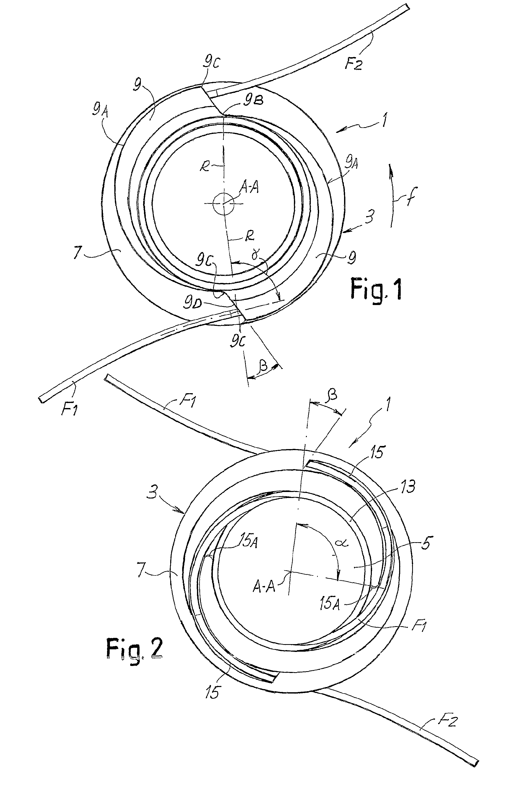
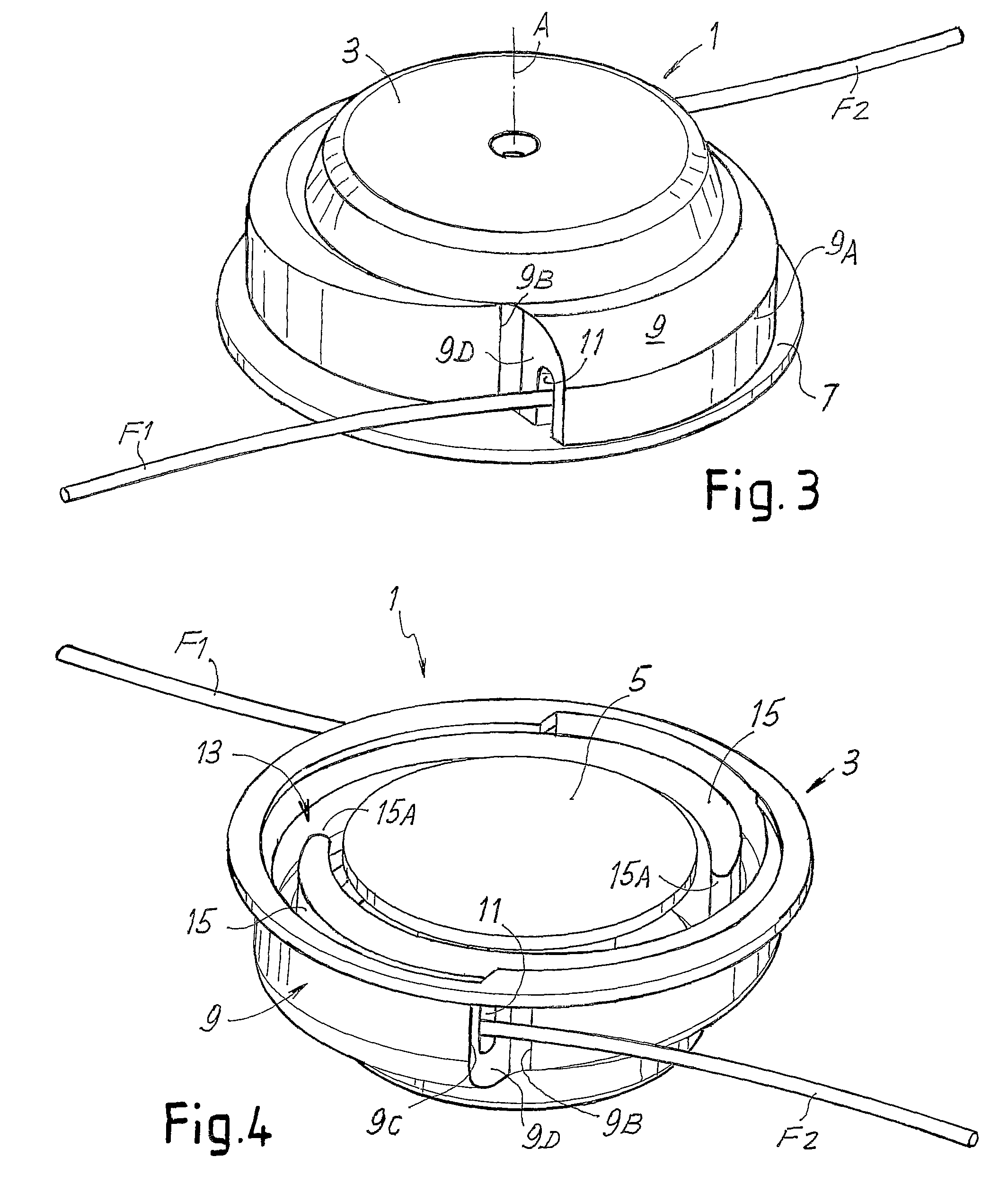
[0033]With initial reference to FIG. 1 to 4, in a first embodiment the grass-cutting head according to the invention, indicated as a whole with 1, has a body 3 composed of a main part substantially in the form of a casing, shown in FIGS. 1 to 4, and optionally a closing cover, not shown, which defines with the cup portion, a compartment 13 to house a spool, indicated schematically with 5 (FIGS. 2 and 4), on which one or more cutting lines F1, F2, are wound. Externally, the body 3 of the grass-cutting head 1 has a substantially circular extension in a top plan view, the maximum diameter of which is defined by the diameter of a circular flange 7. Extending under the circular flange 7, with basic conformation with a substantially circular section of the body 3, are two projections indicated with 9.

[0034]These projections have an approximately spiral development, in the sense that they are defined by an external curvilinear surface 9A which moves gradually away from the body of the head...


PUM


Abstract

The grass-cutting head (101) has a body (103) forming a housing for at least one spool of cutting line (F1; F2), provided with at least one outlet hole (111) of an end of the cutting line wound on said spool positioned inside the head. For each outlet hole, a guide channel for the cutting line is also provided, extending from the inside of the housing towards the hole and having an inclined trend, gradually moving away from said axis of rotation.

Description

TECHNICAL FIELD[0001]The present invention relates to a grass-cutting head for cutting vegetation, and more specifically to a grass-cutting head of the line type, that is, in which the cutting member is composed of a line projecting radially from the head, and which cuts the surrounding vegetation through centrifugal force.STATE OF THE ART[0002]For gardening jobs, both at amateur and professional level, grass-cutting heads are commonly used to cut grass and other vegetation, provided with cutting lines projecting radially from a main body of the head and which, thanks to the centrifugal force exerted thereon and to the rapid rotation of the head about the axis thereof, cut the vegetation.[0003]Examples of cutting heads of this type are described in the following United States patents: U.S. Pat. No. 4,097,991, U.S. Pat. No. 4,104,797, U.S. Pat. No. 4,145,809, U.S. Pat. No. 4,161,820, U.S. Pat. No. 4,259,782, U.S. Pat. No. 4,203,212, U.S. Pat. No. 4,274,201, U.S. Pat. No. 4,651,421, U...

Claims


Application Information

Patent Timeline
Patent Type & Authority Patents(United States)
IPC IPC(8): A01D34/416
CPCA01D34/4163A01D34/4166
Inventor ARNETOLI
Owner ARNETOLI MOTOR
Why Eureka
Try Eureka