
Device for the earthquake-resistant mounting of a partition

a technology for partitions and mounting devices, which is applied in the direction of walls, buildings, constructions, etc., can solve the problem of limited device cost with respect to a conventional assembly, and achieve the effect of limited device cos

Active Publication Date: 2011-06-28
PLACOPLATRE SA
View PDF34 Cites 31 Cited by
  • Summary
  • Abstract
  • Description
  • Claims
  • Application Information

AI Technical Summary

Benefits of technology

[0004]The object of the present invention therefore is to provide a device for the earthquake-resistant mounting of a partition enabling a partition, even when loaded, to resist the stresses undergone during an earthquake. The partition is advantageously easy to mount. Preferably the device also makes it possible to keep the fire-resistant and acoustic properties of a similar “conventionally” constructed partition, and the additional cost of the device is limited with respect to a conventional assembly.
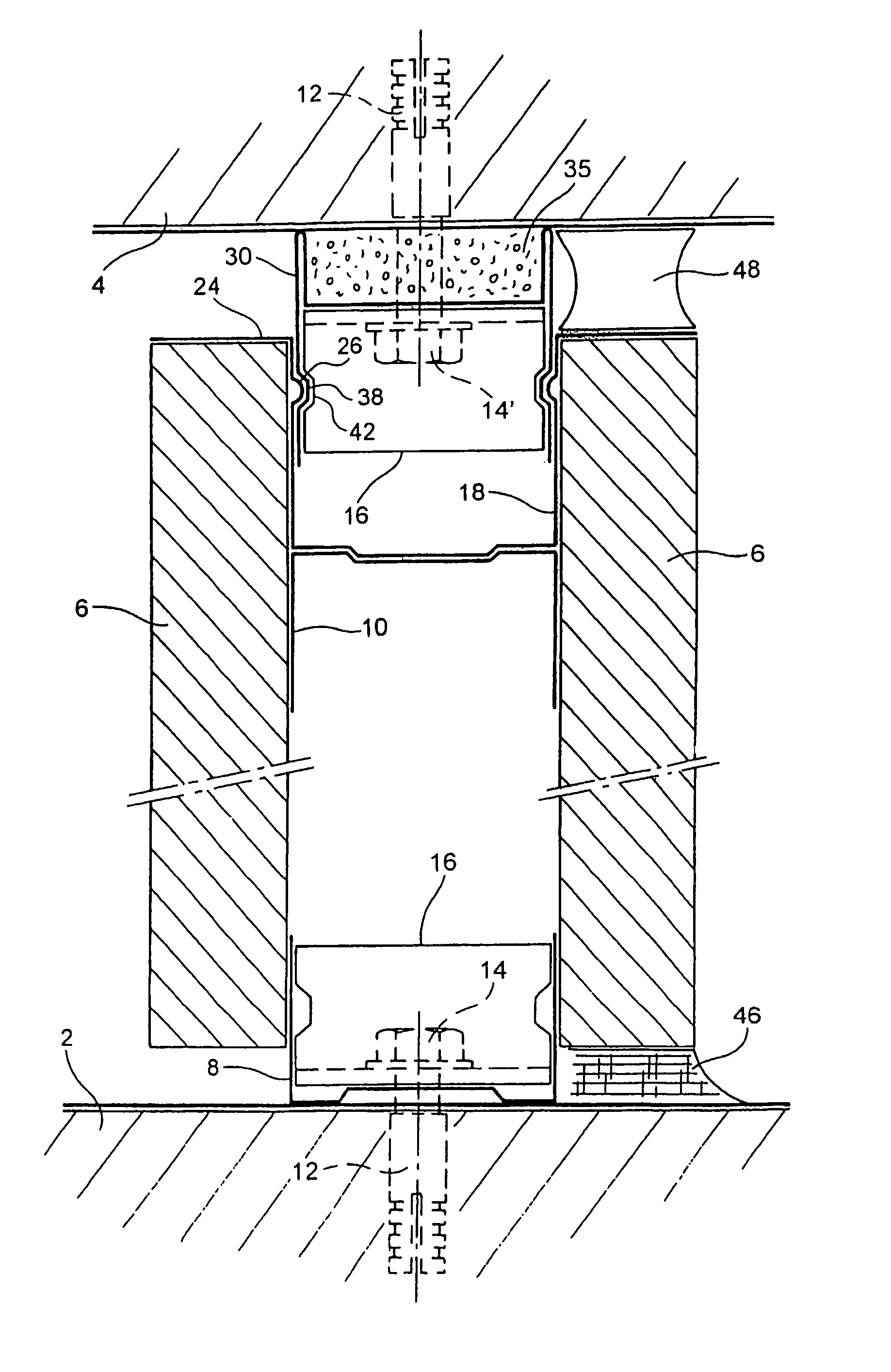
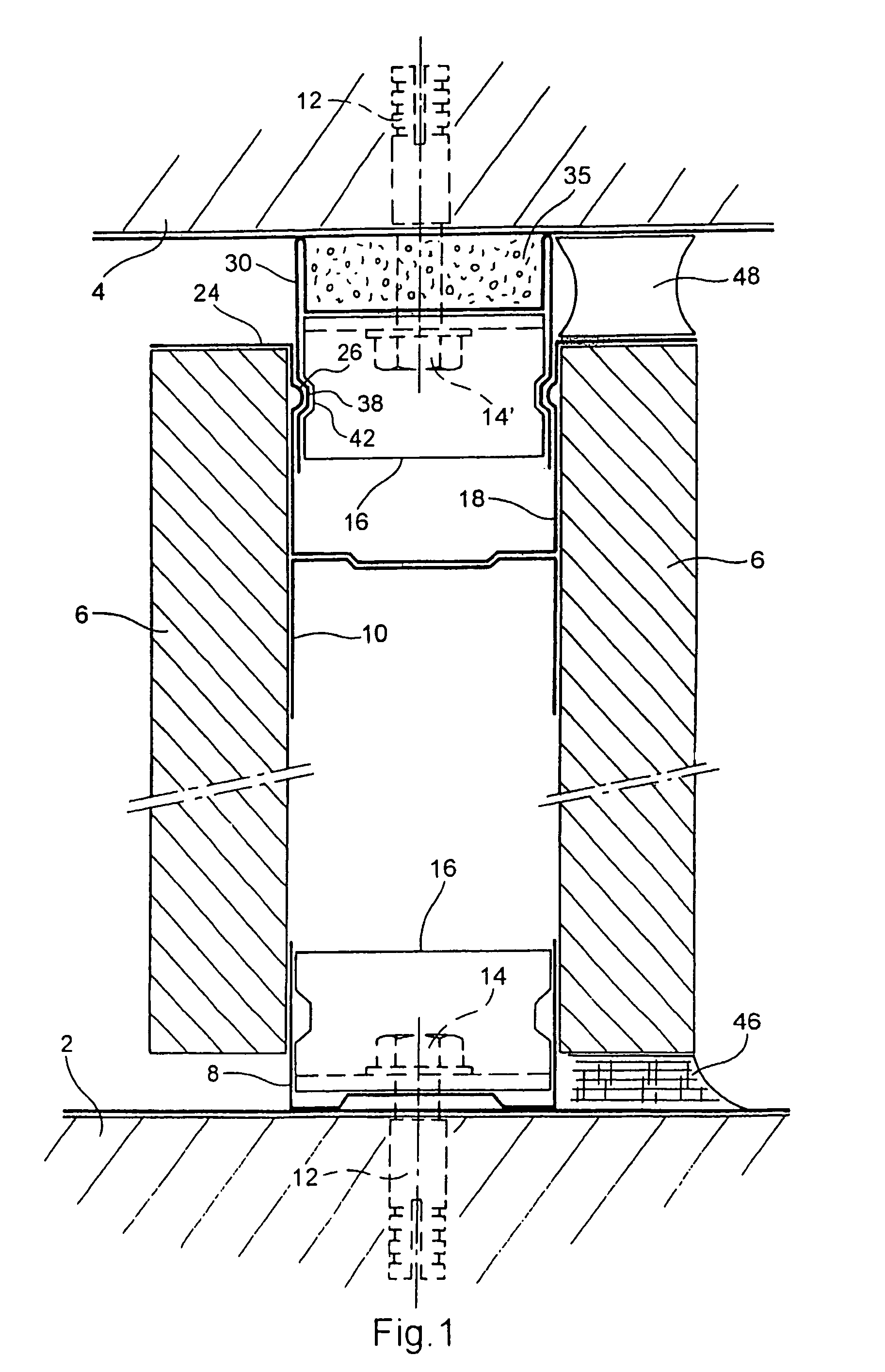
[0007]This device enables the upper rail to be uncoupled from the ceiling. When the device is implemented to produce a partition, the upper rail receiving the covering is not connected to the ceiling but is connected to a member (termed slide here) which can be moved vertically with respect to a holding and guiding member (termed top runner here) itself fixed to the ceiling. Such a device may thus be placed adjacent to a ceiling, at the top of a partition, to enable the latter to take the accelerations undergone during an earthquake without damage, or at least to limit the damage. During the mounting of the partition, the snap-fitting means provided on the slide and on the top runner may be engaged such that the slide is held onto the top runner. As these snap-fitting means are reversible, when stress is applied due for example to an earthquake or to a change in load, the slide can move with respect to the top runner.
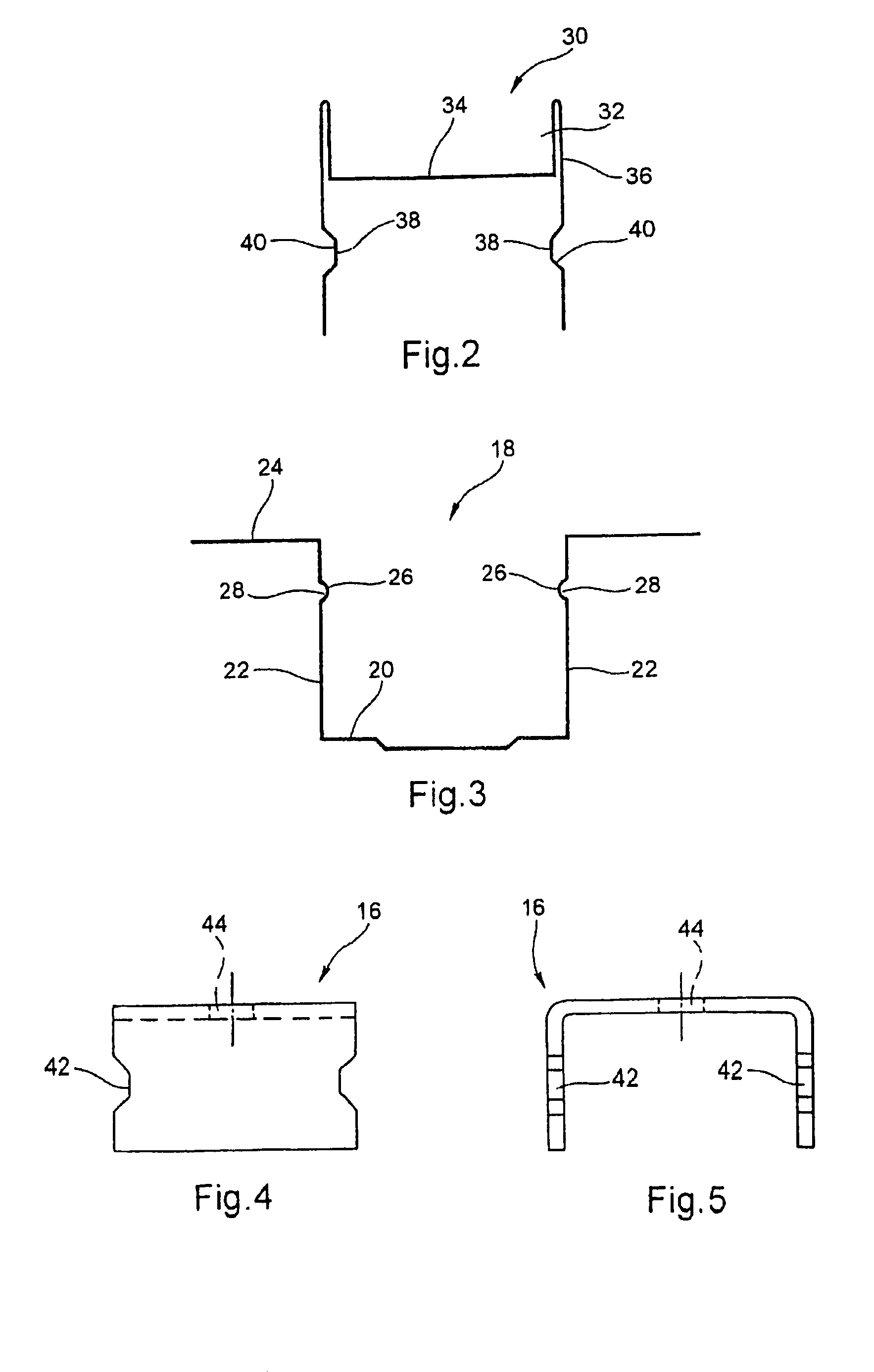
[0008]In one embodiment, the top runner is for example in the form of a rail of profiled section comprising two side flanges extending parallel to the arms of the U-section of the slide and within those arms. Here the top runner is substantially in the form of a rail of profiled section of the type used as upper rail. Preferably, each of the side flanges of the top runner and each of the arms of the U-section of the slide comprises a boss projecting inwardly respectively from the flanges and from the arms, the bosses of the slide being adapted, when in resting position, to locate in the bosses of the top runner. In this variant embodiment, the slide may come into snap-fitting engagement on the top runner when the latter is fixed to the ceiling. This facilitates the assembly of the partition, or more particularly of its framework, since it is not necessary to support the slide and the upper rail which is joined to it, during the installation of the vertical uprights which afterwards receive the covering boards. The bosses made in the slide and in the top runner may be continuous and thus form grooves over the entire length of the corresponding members or else be discrete and therefore form a discontinuous pattern over the slide and the top runner. However, to allow relative longitudinal sliding between the top runner and the slide during mounting, the bosses made on the top runner preferably form a continues groove.
[0009]To avoid the covering boards rising up to the ceiling during formation of a partition, the slide advantageously comprises at each free end of the arms of its U-section a rim extending outwardly of the U, substantially perpendicular to the arms of the U. During implementation of the device, the covering boards then come into abutment with those rims. This also enables an aesthetic finish of good quality to be provided at the top of the partition. To improve the finish, the device advantageously further comprises an elastic joint adapted to be located between a rim of the slide and the ceiling on which the top runner is fixed. This joint enables the gap appearing between the top of the covering and the ceiling to be hidden.
[0010]The top runner is for example a member of profiled section comprising two side flanges slidingly mounted between the arms of the U-section of the slide and also a housing, disposed between the side flanges, on the opposite side from the slide, and adapted to receive a material having fire-retardant properties. This form of top runner is advantageous since it enables fire resistance to be maintained despite the discontinuity of the covering which appears adjacent the ceiling. The presence of a material in said housing also enables sound-proofing to be provided between the two walls of the partition improving the sound insulation performance of the partition.
[0015]This partition is preferably such that the covering is fixed at its upper portion so as not to extend beyond the slide, thus leaving a free space between the covering and the ceiling, it being possible for said space to be filled by a joint of elastic material. In this manner, the covering of the partition is uncoupled from the ceiling and can be rendered “floating” with respect to the ceiling. To improve the disconnection of the covering boards from the structure of the building, said boards are advantageously also mounted so as to be floating with respect to the lower rail.

Problems solved by technology

Preferably the device also makes it possible to keep the fire-resistant and acoustic properties of a similar “conventionally” constructed partition, and the additional cost of the device is limited with respect to a conventional assembly.

Method used


Image

  • Device for the earthquake-resistant mounting of a partition
  • Device for the earthquake-resistant mounting of a partition
  • Device for the earthquake-resistant mounting of a partition

Examples


Embodiment Construction

[0028]FIG. 1 shows a partition according to the invention in transverse cross-section. This partition is a vertical partition disposed between a floor 2 and a ceiling 4 which form two horizontal planar surfaces. The partition comprises both a framework and plaster covering boards 6. The latter are fixed to the framework in conventional manner known to the person skilled in the art, for example using screws that are not shown. The covering boards 6 may be of any particular thickness. However, in the case in which the partition is adapted to be loaded, that is to say that furniture or other things are fixed to the partition, the boards are preferably of relatively great thickness, for example of the order of 25 mm.

[0029]The framework of the partition comprises a lower rail 8 and an upper rail 10 in conventional manner. The lower rail 8 is a rail of U-section profile and is fixed to the floor 2. The base of the U of the rail of profiled section is directed towards the floor 2 whereas t...


PUM


Abstract

Device for the earthquake-resistant mounting of a partition between a floor (2) and a ceiling (4). The partition includes: a frame having (i) a lower runner (8) and an upper runner (10) which are essentially horizontal, and (ii) essentially-vertical studs which connect the upper and lower runners; and a coating (6) which is fixed to the frame. The device includes: a contoured slide (18) which is intended to be solidly connected to the upper runner (10) and which has an essentially-U-shaped cross-section, and a top rail (30) which is intended to be fixed to the ceiling (4) and partially housed in the slide (18) between the arms of the U-shaped section thereof. The slide (18) and the top rail (30) are mounted such that they can move vertically in relation to one another. In addition, reversible detent elements are also provided between the slide (18) and the top rail (30).

Description

BACKGROUND OF THE INVENTION[0001]The present invention relates to a device for the earthquake-resistant mounting of a partition, in particular a partition of plaster boards, as well as to a partition made with such a device.[0002]A partition of plaster boards is generally mounted on a metal structure termed “framework” hereinafter. The mounting of a vertical partition between a floor and a horizontal ceiling is considered here. The metal structure mentioned then conventionally comprises an upper rail fixed to the ceiling, a lower rail disposed in the same vertical plane as the upper rail and fixed onto the floor, as well as vertical uprights regularly spaced apart and each fixed by their ends onto the upper and lower rails. The plaster boards are then mounted on the vertical uprights and also the horizontal rails (upper and lower), for example by screwing.[0003]Such a partition, in the unloaded state, performs satisfactorily during tests on earthquake resistance provided the attachm...

Claims


Application Information

Patent Timeline
IPC IPC(8): E04B2/82E04B2/74
CPCE04B2/825E04B2/7411E04B2/82E04B2/72
Inventor KLEIN, JEAN-PIERRE
Owner PLACOPLATRE SA
Learn More