
Vehicular transmission

a technology of transmission and shift drum, applied in the direction of gearing control, gearing elements, gearing, etc., can solve the problems of large engagement noise, large engagement noise, and discomfort of occupants, and achieve the effect of preventing large engagement noise, reducing rotational speed, and increasing rotational resistance acting on the shift drum center

Active Publication Date: 2011-06-28
HONDA MOTOR CO LTD
View PDF5 Cites 7 Cited by
  • Summary
  • Abstract
  • Description
  • Claims
  • Application Information

AI Technical Summary

Benefits of technology

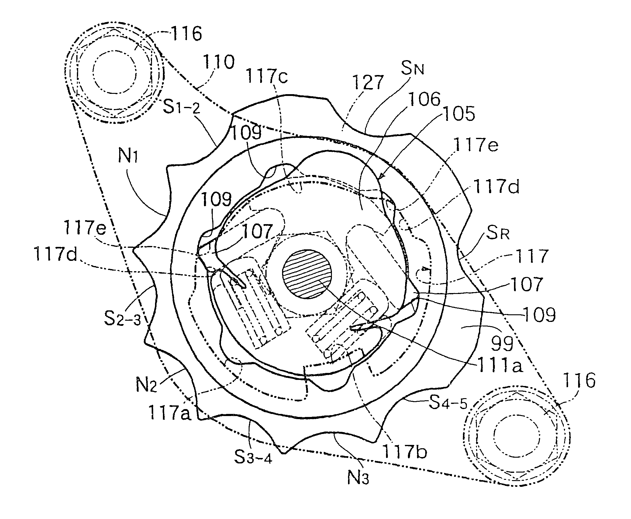
[0013]In accordance with the first aspect of the present invention, when the shifters rotated with the main shafts or the countershaft are slidably moved in order to select the established state of the gear trains, the drum stopper arm engages the half neutral notch, so that rotational resistance acting on the shift drum center can be temporarily increased and the rotational speed can thereby be temporarily reduced. This allows timing of the shifter engaging the gear train to be established to be retarded. The difference in speed between the shifter and the gears to be engaged with the shifter can thereby be made relatively small, so that the engagement noise can be prevented from becoming large.
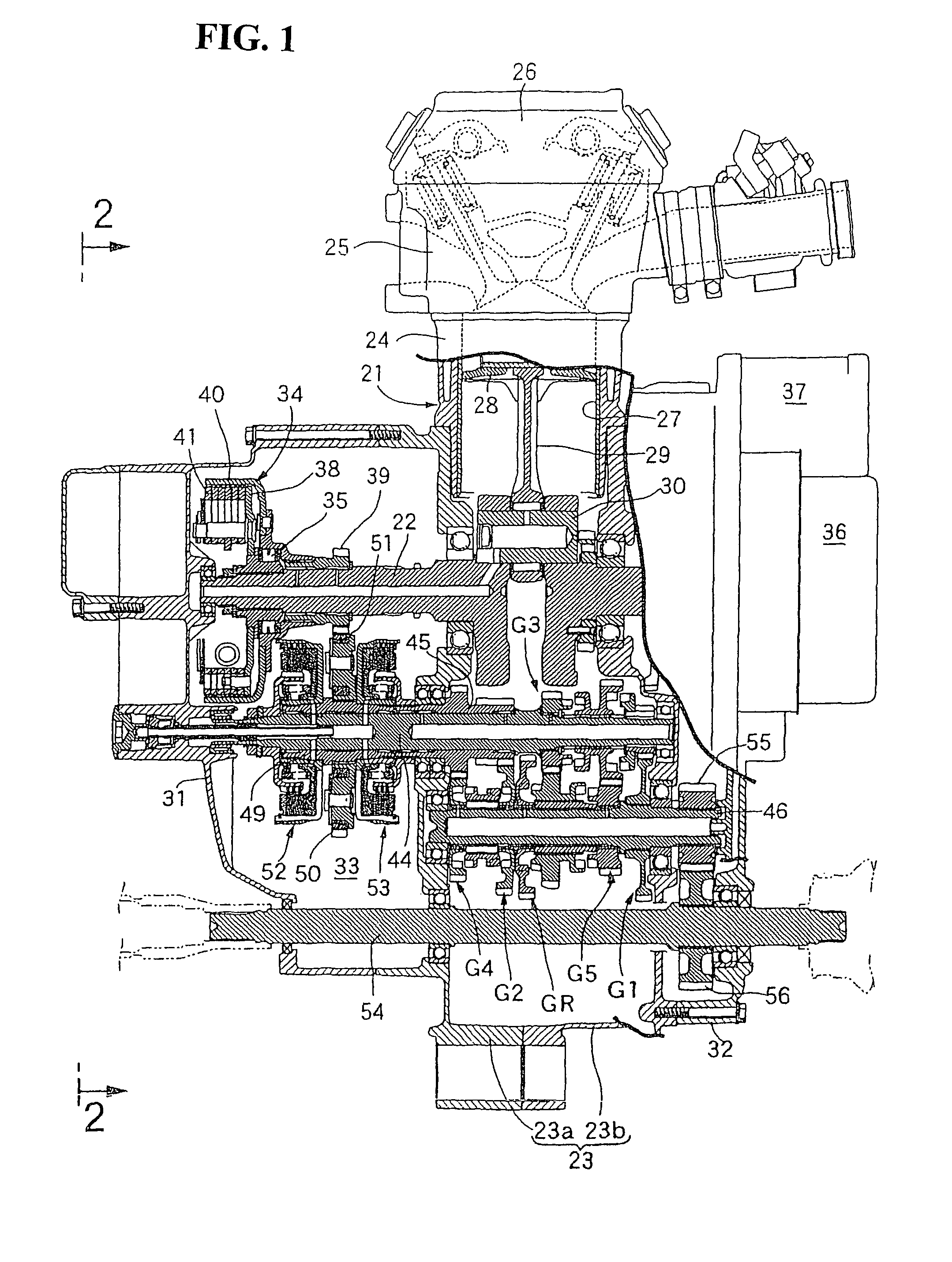
[0014]In accordance with the second aspect of the present invention, when the shifters rotated with the first main shaft are slidably moved in order to select the established state of the gear trains in a condition, in which the power drive from the engine to the first main shaft is shut down with the power drive from the engine to the second main shaft transmitted, the drum stopper arm engages the half neutral notch, so that the rotational resistance acting on the shift drum center can be temporarily increased and the rotational speed can thereby be temporarily reduced. This allows timing of the shifter engaging the gear train to be established to be retarded. Accordingly, in a condition in which both idle gears are rotating as a result of establishment of the gear train disposed between the second main shaft and the countershaft, a difference in speed between the shifter and relative rotation of the gears with which the shifter is engaged, which occurs as the first main shaft is rotated together because of the bearings disposed between the first and second main shaft or viscosity of lubricant packed, can be made relatively small. Accordingly, the engagement noise can be prevented from becoming large.
[0015]In accordance with the third aspect of the present invention, when the shifter rotated with the countershaft is slidably moved in order to select the established state of the gear trains in a condition, in which the power drive from the engine to the second main shaft is shut down with the power drive from the engine to the first main shaft transmitted, the drum stopper arm engages the half neutral notch, so that the rotational resistance acting on the shift drum center can be temporarily increased and the rotational speed can thereby be temporarily reduced. This allows timing of the shifter engaging the gear train to be established to be retarded. Accordingly, in a condition in which the countershaft and the shifter are rotating as a result of establishment of the gear train disposed between the first main shaft and the countershaft, gears of the gear train to be established are also rotated as the second main shaft is rotated together because of the bearings disposed between the first and second main shaft or viscosity of lubricant packed. A difference in speed between these gears and a relative rotational speed of the shifter can be made relatively small. Accordingly, the engagement noise can be prevented from becoming large.
[0016]In accordance with the fourth aspect of the present invention, the drum stopper arm can be quickly engaged with, or disengaged from, the gear train establishment notch and can be maintained in the engaged state with the half neutral notch for a relatively longer period of time.

Problems solved by technology

Consequently, when the established state of the gear trains of the plurality of gear positions is selected, a large engagement noise results because of a relatively large difference in speed between the shifter and a gear to be engaged with the shifter.
Specifically, in such a vehicle, there is produced a large engagement noise that is not operatively associated with an operation performed by an occupant of the vehicle.
This gives the occupant a sense of discomfort.

Method used


Image

  • Vehicular transmission
  • Vehicular transmission
  • Vehicular transmission

Examples


first embodiment

[0101]Effects of the present invention will be described below. The first and third shifters 72, 74 rotated with the first main shaft 44 and the countershaft 46 are slidably moved toward a side, in which the first shifter 72 is disengaged from one of the first and third speed drive idle gears 57, 59 and engaged with the other idle gear, and the third shifter 74 is disengaged from one of the second and fourth speed driven idle gear 64, 66, and engaged with the other idle gear, the first and third speed drive idle gears 57, 59 being disposed on either side of the first shifter 72 and the second and fourth speed driven idle gear 64, 66 being disposed on either side of the third shifter 74. At this time, the first and third shift forks 91, 93 are guided along the neutral portions 96f, 98e formed at the central portions of the communication portions 96c, 98c included in the first and third lead grooves 96, 98 formed on the outer peripheral surface of the shift drum 95, the neutral portio...

second embodiment

[0106]Referring to FIG. 20 showing the present invention, of the notches SR, SN, S1-2, S2-3, S3-4, S4-5, N1, N2, and N3, the reverse positioning notch SR, the neutral positioning notch SN, the first-second speed positioning notch S1-2, the second-third speed positioning notch S2-3, the third-fourth speed positioning notch S3-4, and the fourth-fifth speed positioning notch S4-5 may each be formed into a V-shaped recess, while the neutral notches N1, N2, N3 may each be formed into an arcuate recess.

[0107]According to the second embodiment of the present invention, engagement of the drum stopper arm 100 with, and disengagement of the same from, each of the notches SR, SN, S1-2, S2-3, S3-4, and S4-5, can be made quickly and the drum stopper arm 100 can be made less easy to leave the neutral notches N1, N2, N3. The engagement state of the drum stopper arm 100 can thereby be maintained for a relatively longer period of time and the neutral state can be maintained for a relatively longer p...


PUM


Abstract

A vehicular transmission includes a shift drum center with a plurality of gear train establishment notches disposed, equally spaced apart from each other, on the outer periphery thereof. The gear train establishment notches establish a specific gear train selected from among a plurality of gear trains by selectively engaging a drum stopper arm therein. The shift drum center further includes half neutral notches to be engaged with the drum stopper arm. The half neutral notches are disposed on the outer periphery of the shift drum center and at a central portion between each pair of the gear train establishment notches, respectively. The resulting configuration effectively suppresses an engagement noise during changing of a gear position through a sliding motion of a shifter.

Description

CROSS-REFERENCE TO RELATED APPLICATION[0001]The present application claims priority under 35 U.S.C. §119 to Japanese Patent Application No. 2006-270040, filed Sep. 29, 2006, the entire contents of which are hereby incorporated by reference.BACKGROUND OF THE INVENTION[0002]1. Field of the Invention[0003]The present invention relates to a vehicular transmission including a main shaft, a countershaft, gear trains of a plurality of gear positions, a shift drum, a shift drum center, a drum stopper arm, and an intermittent feed mechanism. Specifically, the main shaft can receive power transmitted from an engine. The countershaft is connected to a drive wheel. The gear trains of the plurality of gear positions are disposed between the main shaft and the countershaft, allowing the plurality of gear positions to be selectively established. The shift drum has a lead groove formed on an outer periphery thereof for selecting an established state of the gear trains of the plurality of gear posit...

Claims


Application Information

Patent Timeline
Patent Type & Authority Patents(United States)
IPC IPC(8): F16H59/00
CPCF16H63/18F16H61/32Y10T74/19251Y10T74/19279
Inventor SOTANI, HIROSHIMIZUNO, KINYAHAMAOKA, SEIJIKITTAKA, EIJI
Owner HONDA MOTOR CO LTD
Learn More