Bulb type detector for dimmer circuit and inventive resistance and short circuit detection

a detector and dimmer circuit technology, applied in the direction of electric variable regulation, process and machine control, instruments, etc., can solve the problems of ineffectiveness, complex methods, and high cost of known methods, and achieve the effect of not being effective, not being easy to detect, and being easy to us

Inactive Publication Date: 2011-06-28
ENOCEAN
View PDF29 Cites 11 Cited by
  • Summary
  • Abstract
  • Description
  • Claims
  • Application Information

AI Technical Summary

Benefits of technology

[0007]The method of utilizing the RC circuit time constant to measure a resistance is a separately inventive way of measuring resistance for any application. Further, the detection of a short or open circuit by looking at the RC time constant is also separately inventive for any application.

Problems solved by technology

To date, the prior art has not provided a method of identifying whether a bulb in a particular outlet is an incandescent or a fluorescent bulb.
In addition, while several methods are known for determining the resistance of an electrical component, and for determining a short or open circuit on a portion of a circuit, those known methods have been relatively expensive, complex, and not necessarily effective.

Method used


Image

  • Bulb type detector for dimmer circuit and inventive resistance and short circuit detection
  • Bulb type detector for dimmer circuit and inventive resistance and short circuit detection
  • Bulb type detector for dimmer circuit and inventive resistance and short circuit detection

Examples


Embodiment Construction

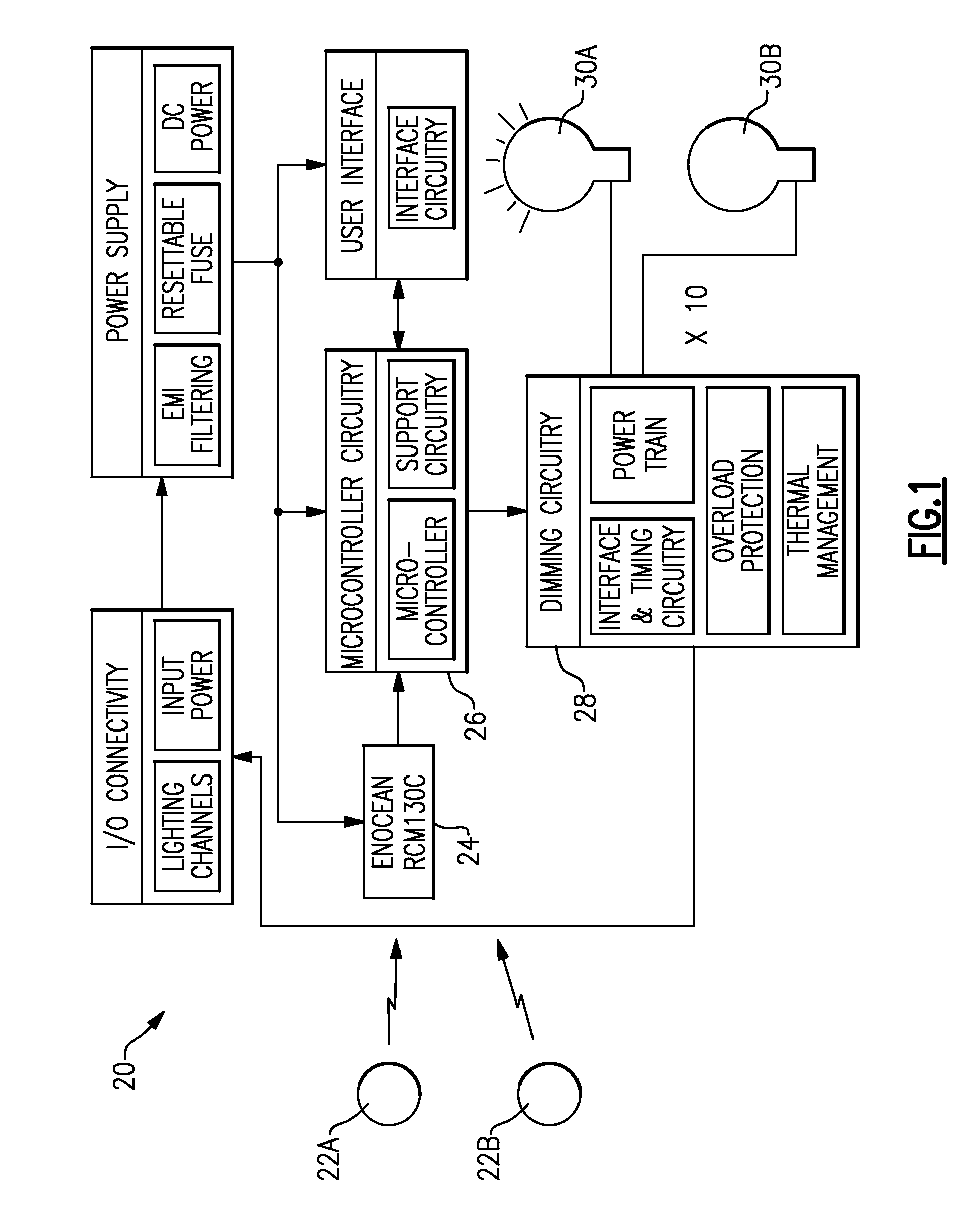
[0013]FIG. 1 shows a lighting control circuit 20 for a building. As shown, a plurality of switches 22A, 22B, etc. communicate through a wireless connection to a multi-channel receiver 24. This receiver may be as available from Enocean, and available for example under its Product No. RCM130C. The use of a wireless receiver and wireless switches are not limiting on this invention, but only mentioned as one possible type of system.

[0014]The receiver 24 communicates with a microcontroller 26, which in turn communicates with dimmer circuit 28. The dimmer circuits 28 (only one of which is shown) control the intensity of lights 30A, 30B, etc.

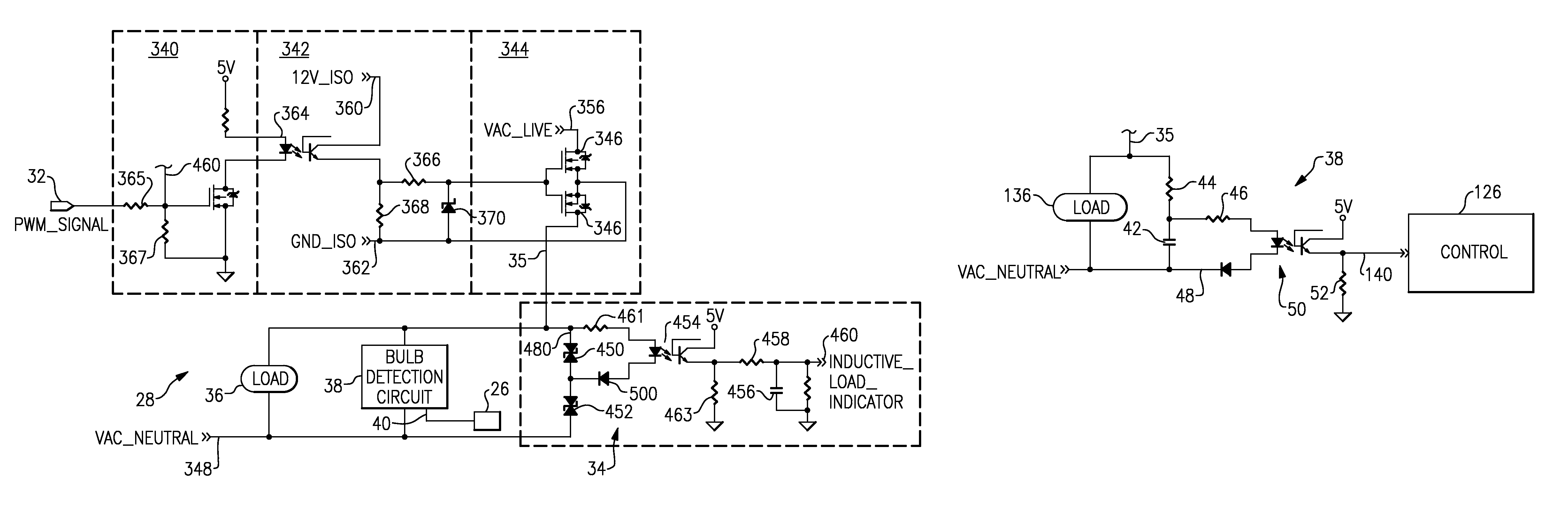
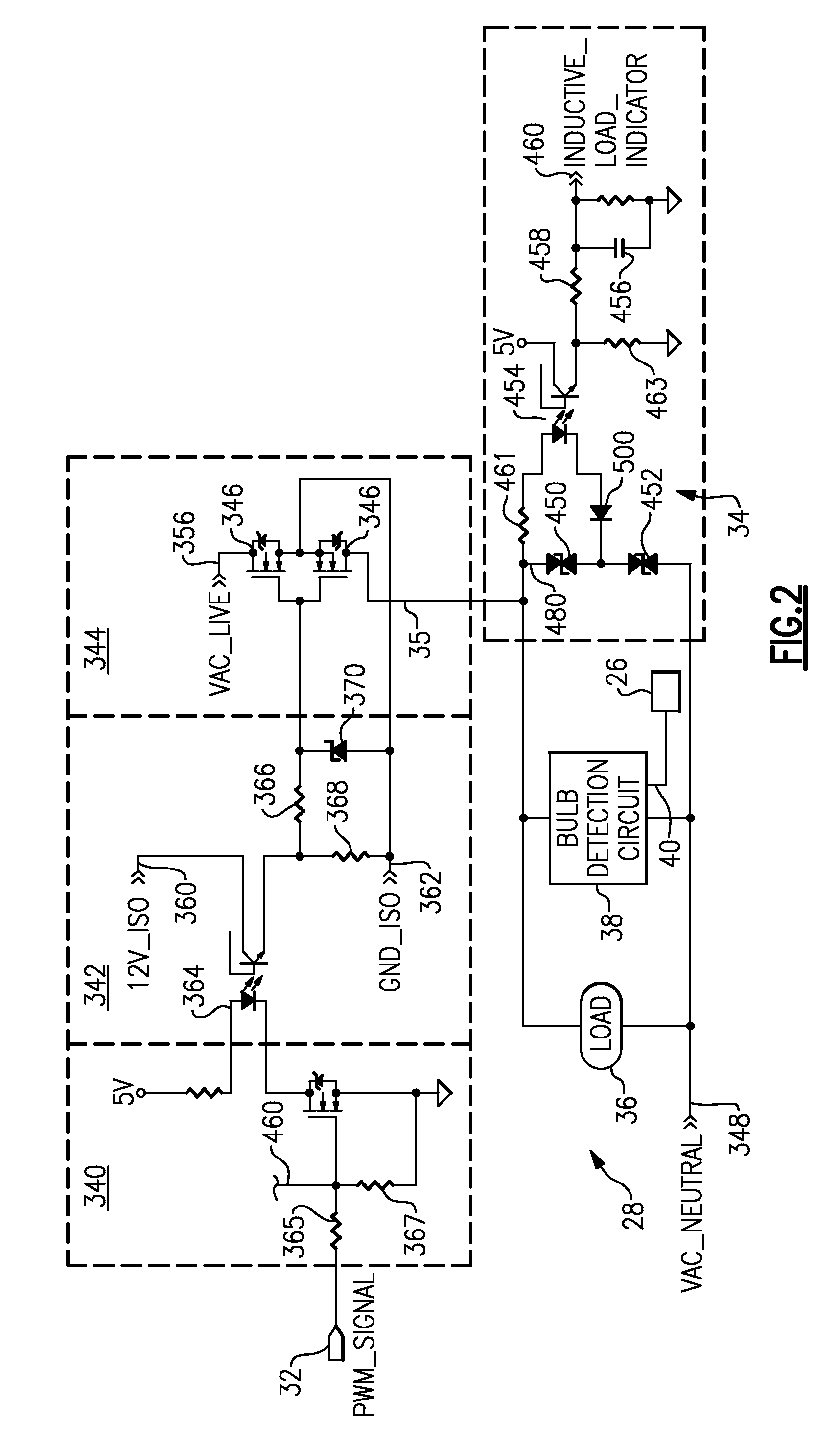
[0015]FIG. 2 schematically shows a dimmer circuit, such as the main circuitry 28 as shown in FIG. 1. A pulse width modulation control from a microcontroller, such as microcontroller 26, communicates into a dimmer circuit 28 to control the power supplied to an outlet line 35. Outlet line 35 communicates to a load 36. An inductive load sensing circuit 34...


PUM


Abstract

A bulb detection circuit is associated with a dimmer circuit for a lighting system. The bulb detection circuit is operable to detect whether an incandescent or a fluorescent bulb is received in an electric light socket. The socket may be hardwired to the circuit, or could be plugged into an electrical outlet. The bulb detection circuit may utilize a separately inventive method of measuring the resistance by looking at an RC circuit time constant. Further, the bulb detection circuit may utilize a separately inventive method of identifying a short circuit by again looking at the RC circuit time constant.

Description

BACKGROUND OF THE INVENTION[0001]This application relates to a lighting control system including a dimmer circuit, which identifies the type of bulb connected to the dimmer circuit. In addition, the bulb detection circuit relies on a separately inventive method of determining a resistance, and a separately inventive method of determining short or open circuits.[0002]Lighting control systems are known, and may include dimmer circuits. As known, a dimmer circuit limits the light intensity of a bulb in some manner.[0003]In modern buildings, there may be incandescent bulbs and fluorescent bulbs. Historically, residential lighting was provided more by incandescent bulbs, however, fluorescent bulbs are being mandated by government regulation.[0004]To date, the prior art has not provided a method of identifying whether a bulb in a particular outlet is an incandescent or a fluorescent bulb.[0005]In addition, while several methods are known for determining the resistance of an electrical com...

Claims


Application Information

Patent Timeline
Patent Type & Authority Patents(United States)
IPC IPC(8): H05B37/02G01R27/08
CPCH05B39/048H05B41/3924H05B41/36H05B39/10
Inventor XU, JIANIOTT, JEFFREYBARNETT, THOMAS ALAN
Owner ENOCEAN
Why Eureka
Try Eureka