System and method of extending regenerative braking in a hybrid electric vehicle

a hybrid electric vehicle and regenerative braking technology, applied in the direction of engine-driven generators, machines/engines, propulsion using engine-driven generators, etc., can solve the problems of objectionable switching and additional wear, and achieve the effect of reducing mechanical wheel brake wear, capturing and storing energy, and increasing the state of charge of batteries

Inactive Publication Date: 2011-07-05
FORD GLOBAL TECH LLC
View PDF38 Cites 14 Cited by
  • Summary
  • Abstract
  • Description
  • Claims
  • Application Information

AI Technical Summary

Benefits of technology

[0001]A hybrid electric vehicle may perform regenerative braking operations during vehicle deceleration in order to capture and store energy that would otherwise be lost as a result of performing mechanical braking operations. In particular, during deceleration an electric energy conversion device (e.g. generator) may absorb kinetic energy generated as a result of the vehicle deceleration and may convert the kinetic energy to electric energy which may be used to increase the state of charge of a battery. Performing regenerative braking operations may be desirable beyond recouping energy because the hybrid electric vehicle may be decelerated with minimal or no negative torque supplied by the mechanical wheel brakes. Thus, reducing wear on the mechanical wheel brakes. During vehicle operation, regenerative braking may be in favor of mechanical braking via wheel brakes due to the battery being charged to capacity. Regenerative braking may be resumed when electric energy has been depleted from the battery so that the battery has room to store more electric energy. The incessant switching between regenerative braking and mechanical braking may be sensed by the vehicle operator and the vehicle operator may perceive the switching to be objectionable. Further, additional use of the mechanical wheels brakes may cause additional wear over time.

Problems solved by technology

The incessant switching between regenerative braking and mechanical braking may be sensed by the vehicle operator and the vehicle operator may perceive the switching to be objectionable.
Further, additional use of the mechanical wheels brakes may cause additional wear over time.
However, the inventors herein have recognized some issues relating to the above approach.
Thus, although the above approach may extend regenerative braking capabilities for a period, eventually mechanical wheel brakes may be used earlier than desired to decelerate the vehicle

Method used


Image

  • System and method of extending regenerative braking in a hybrid electric vehicle
  • System and method of extending regenerative braking in a hybrid electric vehicle
  • System and method of extending regenerative braking in a hybrid electric vehicle

Examples


Embodiment Construction

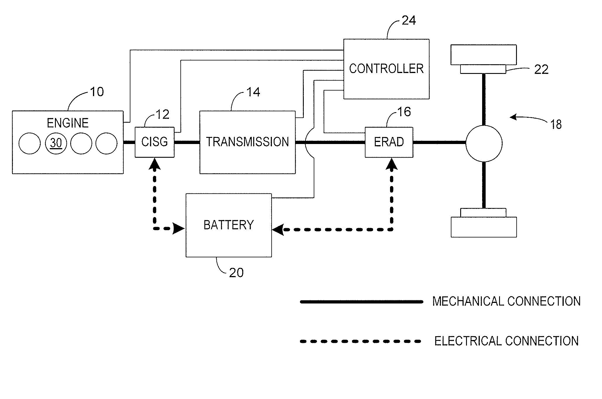
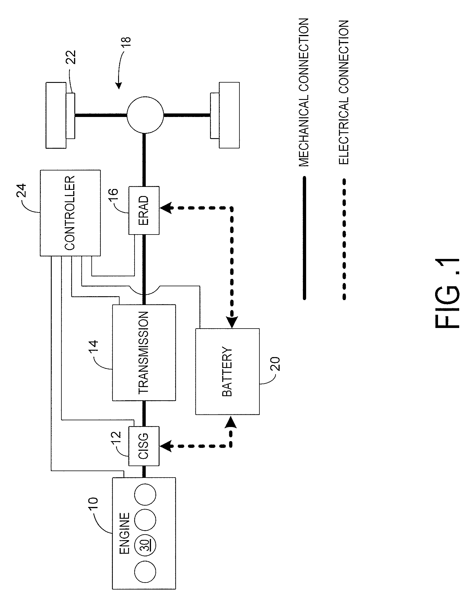
[0010]FIG. 1 illustrates an exemplary embodiment of a hybrid propulsion system for a vehicle. The hybrid propulsion configuration may be used with the disclosed approach for providing improved vehicle braking over an extended duration that maintains a high state of charge of the battery and reduces wear on the mechanical wheel brakes. In this example, the hybrid propulsion system may include an Atkinson cycle internal combustion engine (ICE) 10 having one or more cylinders 30, transmission 14, final drive / wheels 18 or other suitable device for delivering propulsive force to the ground surface, and two electric energy conversion devices 12 and 16. Each of wheels 18 may include wheel brake device 22.

[0011]Electric energy conversion devices 12 and 16 may operate as motors and convert electric energy into output torque. Further, electric energy conversion devices 12 and 16 may operate as generators and convert torque into electric energy. Note that electric energy conversion devices 12 ...


PUM


Abstract

A method of generating brake force to decelerate a vehicle is provided. The method includes during a deceleration condition, generating brake torque via a downstream electric energy conversion device to generate electric energy storable in the battery; and rotating the internal combustion engine via torque output from an upstream electric energy device to deplete electric energy from the battery.

Description

BACKGROUND AND SUMMARY[0001]A hybrid electric vehicle may perform regenerative braking operations during vehicle deceleration in order to capture and store energy that would otherwise be lost as a result of performing mechanical braking operations. In particular, during deceleration an electric energy conversion device (e.g. generator) may absorb kinetic energy generated as a result of the vehicle deceleration and may convert the kinetic energy to electric energy which may be used to increase the state of charge of a battery. Performing regenerative braking operations may be desirable beyond recouping energy because the hybrid electric vehicle may be decelerated with minimal or no negative torque supplied by the mechanical wheel brakes. Thus, reducing wear on the mechanical wheel brakes. During vehicle operation, regenerative braking may be in favor of mechanical braking via wheel brakes due to the battery being charged to capacity. Regenerative braking may be resumed when electric ...

Claims


Application Information

Patent Timeline
Patent Type & Authority Patents(United States)
IPC IPC(8): B60W20/00B60W30/18
CPCB60K6/448B60K6/485B60W30/18127B60W30/18136F02D13/04B60L1/02B60L11/123B60L11/14B60L11/1861B60L15/2009B60K1/02Y02T10/642B60W10/08B60W10/26B60W20/00B60W2710/0616Y02T10/6226Y02T10/6243B60L2240/421B60L2240/423B60L2240/441B60L2240/443B60L2240/445B60L2270/12Y02T10/7077Y02T10/7044Y02T10/7005Y02T10/705Y02T10/7275Y02T10/6217B60K6/20Y02T10/72B60L50/61B60L50/16B60L58/12B60L58/15Y02T10/62Y02T10/64Y02T10/70Y02T10/7072B60W10/24B60W20/13B60W2510/083
Inventor YAMAZAKI, MARK STEVENRAMASWAMY, DEEPA
Owner FORD GLOBAL TECH LLC
Why Eureka
Try Eureka