Controller and control method for hybrid vehicle

a control method and hybrid technology, applied in electric control, machines/engines, transportation and packaging, etc., can solve the problems of clogging the filter, limited opportunity and inability to execute catalyst temperature increase control at necessary timings, etc., to achieve the effect of increasing the temperature of the three-way catalyst device, facilitating execution, and facilitating the execution

Active Publication Date: 2020-02-13
TOYOTA JIDOSHA KK
View PDF0 Cites 5 Cited by
  • Summary
  • Abstract
  • Description
  • Claims
  • Application Information

AI Technical Summary

Benefits of technology

[0008]Fuel gas generated through combustion of air-fuel mixture in the cylinders flows through the exhaust passage of the internal combustion engine during the combustion operation. When the air-fuel mixture is introduced unburned into the exhaust passage without burning the air-fuel mixture in the cylinders, the air-fuel mixture burns in the three-way catalyst device, thereby increasing the temperature of the three-way catalyst device (catalyst temperature). During the execution of the fuel introduction process as described above, the air-fuel mixture in the cylinders needs to be delivered to the exhaust passage by rotating the crankshaft of the internal combustion engine with external power. In the catalyst temperature increase control, the catalyst temperature increase control unit of the controller for the hybrid vehicle as described above executes the motoring control of rotating the crankshaft of the internal combustion engine with the power of the motor in a state in which the combustion of the internal combustion engine is stopped and executes the fuel introduction process during the execution of the motoring control. In such a case, when the motoring control is executable, the fuel introduction process can be executed. Thus, the opportunity to execute the catalyst temperature increase control can be easily obtained.
[0009]The hybrid vehicle may include an electric generator that generates electric power when receiving power of the internal combustion engine and include a battery capable of storing electric power generated by the electric generator and supplying the motor with the stored electric power. In this case, the catalyst temperature increase control unit of the controller for the hybrid vehicle may be configured to execute a charge control of performing a combustion operation of the internal combustion engine before the motoring control starts, thereby causing the electric generator to generate electric power. When the motoring control is executed, the power consumption of the motor decreases the battery state of charge. Thus, it is desired that before the motoring control is started, the charge control be executed to increase the battery state of charge.

Problems solved by technology

Thus, if the deposit is left, the deposited particulates may eventually clog the filter.
However, in such a case, the opportunity to execute the catalyst temperature increase control is limited.
Thus, the catalyst temperature increase control may not be executed at necessary timings.
In such a case, the above-described problem can occur in the same manner.
Thus, regardless of objectives, the above-described problem is common when the catalyst temperature increase control is performed by introducing unburned air-fuel mixture into the three-way catalyst device.
When the motoring control is executed, the power consumption of the motor decreases the battery state of charge.
When the charge control is performed, the combustion of the internal combustion engine consumes fuel.
When the warm-up is incomplete, the friction in the internal combustion engine is large, thereby increasing the power consumption of the motor in the motoring control.

Method used


Image

  • Controller and control method for hybrid vehicle
  • Controller and control method for hybrid vehicle
  • Controller and control method for hybrid vehicle

Examples


first embodiment

[0023]A controller for a hybrid vehicle according to a first embodiment will now be described with reference to FIGS. 1 to 3.

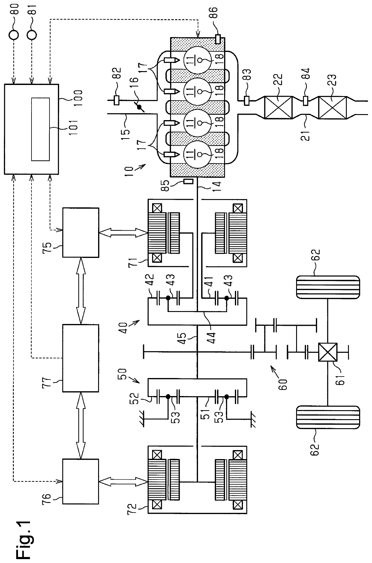
[0024]As shown in FIG. 1, the hybrid vehicle to which the controller of the present embodiment is applied includes a spark-ignition internal combustion engine 10. Also, the hybrid vehicle includes two motor generators serving as a motor and an electric generator, namely, a first motor generator 71 and a second motor generator 72. Further, the hybrid vehicle includes a battery 77, a first inverter 75, and a second inverter 76. The battery 77 stores electric power generated by the first motor generator 71 and the second motor generator 72 when serving as the electric generators. In addition, the battery 77 supplies the stored electric power to the first motor generator 71 and the second motor generator 72 when serving as the motors. The first inverter 75 adjusts the amount of electric power supplied and received between the first motor generator 71 and the batte...

second embodiment

[0051]A controller for a hybrid vehicle according to a second embodiment will now be described in detail with reference to FIG. 4. In the present embodiment, the same reference numerals are given to those components that the same as the corresponding components of the above-described embodiment and detailed description thereof is omitted.

[0052]In the motoring control, the first motor generator 71 consumes electric power. In particular, when warm-up of the internal combustion engine 10 is incomplete, the friction in the internal combustion engine 10 is large. As a result, since the torque necessary to rotate the crankshaft 14 becomes large, the first motor generator 71 consumes an increased amount of electric power in the motoring control. Even after completion of the catalyst temperature increase control, the battery state of charge necessary to restart the internal combustion engine 10 needs to be left. Thus, in a case in which the battery state of charge is less than or equal to a...


PUM


Abstract

A controller configured to control a hybrid vehicle includes a catalyst temperature increase control unit configured to execute a catalyst temperature increase control of increasing a temperature of a three-way catalyst device, a motoring control of rotating a crankshaft of an internal combustion engine with power of a motor in a state in which combustion of the internal combustion engine is stopped, and a fuel introduction process of introducing unburned air-fuel mixture into an exhaust passage by performing fuel injection in the internal combustion engine during the execution of the motoring control.

Description

FIELD[0001]The following description relates to a controller and a control method for a hybrid vehicle including a spark-ignition internal combustion engine in which a three-way catalyst device is arranged in an exhaust passage.DESCRIPTION OF RELATED ART[0002]A spark-ignition internal combustion engine performs combustion by igniting, with a spark of an ignition plug, the mixture of air and fuel introduced into a cylinder. The combustion of some of the fuel in the air-fuel mixture may be incomplete, thereby generating carbonaceous particulate matter (hereinafter referred to as particulates).[0003]U.S. Patent Application Publication No. 2014 / 0041362 discloses an onboard spark-ignition internal combustion engine including a three-way catalyst device arranged in an exhaust passage and a particulate-capturing filter arranged at the downstream side of the three-way catalyst device in the exhaust passage. In such an internal combustion engine, particulates generated in the cylinder are ca...

Claims


Application Information

Patent Timeline
Patent Type & Authority Applications(United States)
IPC IPC(8): B60W20/00B60K6/24B60K6/28B60K6/26F02D41/02F01N3/021F01N3/10F01N3/20F02D41/04
CPCB60Y2200/92B60K6/24B60W20/00B60K6/28F01N3/101B60K6/26F02D41/025B60W2510/244F01N3/021F02D41/042F01N3/2033F02D37/00F02D41/029F02D29/02F01N3/20F01N2250/02F01N2430/00F01N2590/11F01N3/023F01N13/009F02D2250/24F01N2900/1404F01N2900/104B60K6/445B60W10/06B60W10/08B60W20/16B60W2510/0623Y02T10/40Y02T10/62
Inventor NOSE, YUKIIKEDA, YUTOHASHINOKUCHI, HIROFUMISUZUKI, TATSUAKIIKUTA, EIJIMYOJO, KEIICHIANDO, HIROKAZU
Owner TOYOTA JIDOSHA KK
Why Eureka
Try Eureka