Method and system for reducing uplink noise in wireless communication systems

a wireless communication and wireless communication technology, applied in the field of wireless communication, can solve the problems of increasing affecting the reception and detection of the base station receiver, and varying levels of degradation of the radiation signal, so as to reduce the overall noise floor, reduce the output gain level, and reduce the noise contribution

Active Publication Date: 2011-07-05
COMMSCOPE TECH LLC
View PDF15 Cites 29 Cited by
  • Summary
  • Abstract
  • Description
  • Claims
  • Application Information

AI Technical Summary

Benefits of technology

[0006]The present invention provides a technique for reducing the overall noise floor in a wireless communication system, subsystem or network, by reducing the output gain levels of specific uplink antenna transmitters during non-signal time periods (e.g., rest mode) when no communication signals are being conveyed between the mobile unit(s) and base station involved. The output gain level of each such uplink antenna's transmitter is decreased by a predetermined amount, which reduces the noise contribution of that uplink antenna, but also maintains the gain at a high enough level so that a signal can still pass from a mobile unit to the base station via that link, for example, during a call initiation attempt.

Problems solved by technology

In this regard, a problem with cellular communications is that the radiated signals experience varying levels of degradation as they are transported over the radio air interface between a mobile station and a base station.
Unfortunately, a problem with the use of multiple antennas on the uplink (i.e., from the mobile station to the base station) is that each of the uplink antennas represents a noise source to the base station's receiver, and the overall noise floor is increased significantly as a result.
The increased noise level interferes with the base station receiver's reception and detection of weaker signals from mobile stations that are located farther away.
Consequently, service can become unavailable and communications can be blocked or dropped.
However, a disadvantage of this approach is that muting an uplink antenna path increases the network's communication latency, by increasing the time it takes to restore the uplink connection and pass the signal from the mobile station to the base station (e.g., during a call initiation attempt).

Method used


Image

  • Method and system for reducing uplink noise in wireless communication systems
  • Method and system for reducing uplink noise in wireless communication systems
  • Method and system for reducing uplink noise in wireless communication systems

Examples


Embodiment Construction

)

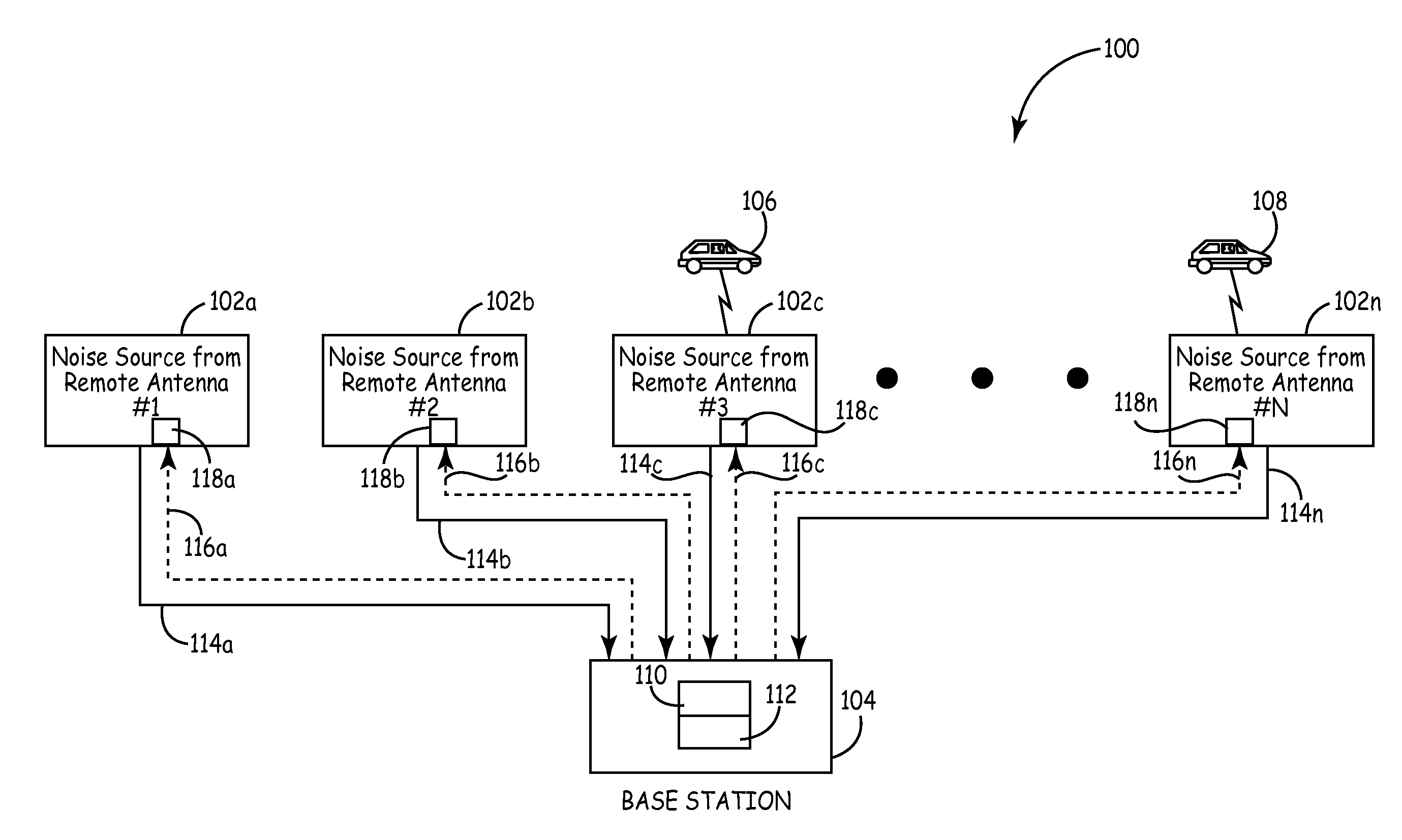
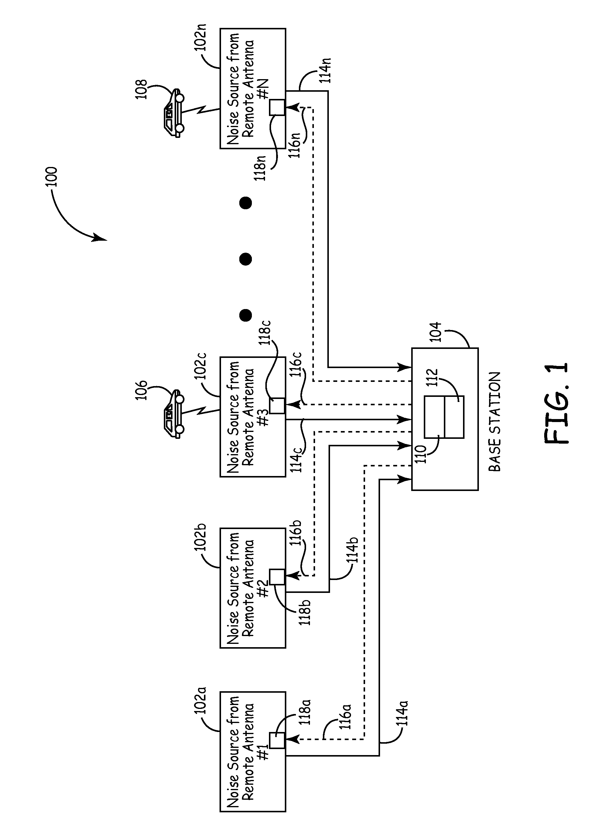
[0010]With reference now to the figures, FIG. 1 depicts a block diagram of an example wireless communication system 100, which can be used to implement one or more embodiments of the present invention. For at least one example embodiment, system 100 can be used to implement a cellular communication system including a network configured with a plurality of cells (e.g., macro-cells, micro-cells, pico-cells, or a combination thereof). More generally, system 100 can be used to implement any suitable wireless communication system, subsystem or network including a plurality of smaller antennas (e.g., at remote locations), and each of the smaller antennas' transmissions contribute a significant amount of noise to the overall noise floor. For clarity, the term “noise floor” may be defined as the measure of a signal created from the sum of all the noise sources and unwanted signals within the system, subsystem or network involved.

[0011]For one or more example embodiments, system 100 represe...


PUM


Abstract

A method and system for reducing the overall noise floor in a wireless communication system, subsystem or network are disclosed, which reduces the output gain levels of specific uplink antenna transmitters during non-signal time periods (e.g., rest mode) when no communication signals are being conveyed between the mobile unit(s) and base station involved. The output gain level of each such uplink antenna's transmitter is decreased by a predetermined amount, which reduces the noise contribution of that uplink antenna, but also maintains the gain at a high enough level so that a signal can still pass from a mobile unit to the base station via that link, for example, during a call initiation attempt.

Description

FIELD OF THE INVENTION[0001]The present invention relates generally to the wireless communications field, and more specifically, but not exclusively, to a method and system for reducing uplink noise in wireless communication systems when multiple uplink antennas are used.BACKGROUND OF THE INVENTION[0002]In certain wireless communication systems, such as for example, cellular communication systems, network capacity and service coverage can be improved by using a plurality of smaller antennas at remote locations where a base station is not needed or desired. For example, such smaller antennas can be used in urban locations where Radio Frequency (RF) signals are degraded or blocked.[0003]In this regard, a problem with cellular communications is that the radiated signals experience varying levels of degradation as they are transported over the radio air interface between a mobile station and a base station. Consequently, in order to extend service coverage and also compensate for such s...

Claims


Application Information

Patent Timeline
Patent Type & Authority Patents(United States)
IPC IPC(8): H04W4/00
CPCH04W72/048H04W72/51
Inventor HERMEL, MICHAEL J.
Owner COMMSCOPE TECH LLC
Why Eureka
Try Eureka