Capacitive Microphone With Integrated Cavity

a technology of capacitors and microphones, applied in the direction of microphone structural associations, loudspeakers, electrical transducers, etc., can solve the problems of limiting the cost cutting measures of microfabrication, the dominant factor of packaging costs of devices, and the high cost associated with silicon microfabrication, so as to reduce the need for wire bonding, save costs for high volume, and reduce costs

Active Publication Date: 2010-05-13
UNIV OF FLORIDA RES FOUNDATION INC
View PDF19 Cites 8 Cited by
  • Summary
  • Abstract
  • Description
  • Claims
  • Application Information

AI Technical Summary

Benefits of technology

[0004]Embodiments of the subject capacitive microphone can be condenser or electret condenser. In a specific embodiment fabricated using PCB-based technology, a 24″×24″ substrate is utilized, which can save costs for high volume. In an embodiment locating the interface electronics within the cavity, a conductive interior surface on the enclosure top, wall, or bottom can be used to connect the backplate to the interface electronics, and connecting to the diaphragm, such that no wire bonds are needed. Reducing the need for wire bonds can reduce costs and improve reliability. In an embodiment, the exterior of the package can be metal-plated and grounded to shield against electromagnetic interference. In accordance with various embodiments of the invention, lower fabrication cost and an integrated package can allow the microphone diaphragm to be much larger. The larger diaphragm can improve sensitivity, increase the sensor capacitance, and reduce the noise floor, resulting in superior performance. Embodiments of the invention can incorporate a large back volume such that the microphone can reduce cavity stiffening effects with respect to silicon devices that are limited to a silicon wafer thickness resulting in improved device performance.

Problems solved by technology

However, the high costs associated with silicon microfabrication currently limits the microfabrication-based cost cutting measures.
The packaging costs of the device can also be a dominant factor.

Method used


Image

  • Capacitive Microphone With Integrated Cavity
  • Capacitive Microphone With Integrated Cavity
  • Capacitive Microphone With Integrated Cavity

Examples


Embodiment Construction

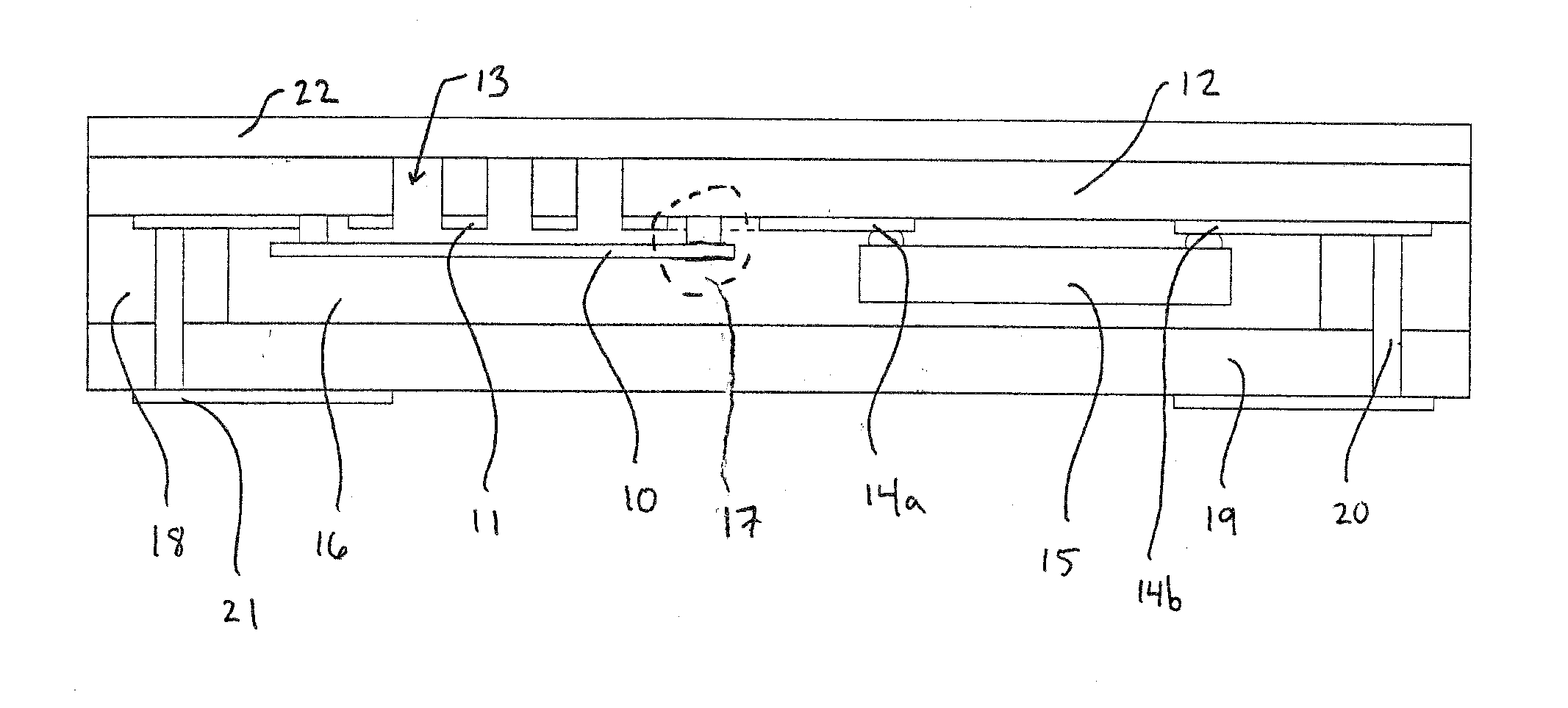
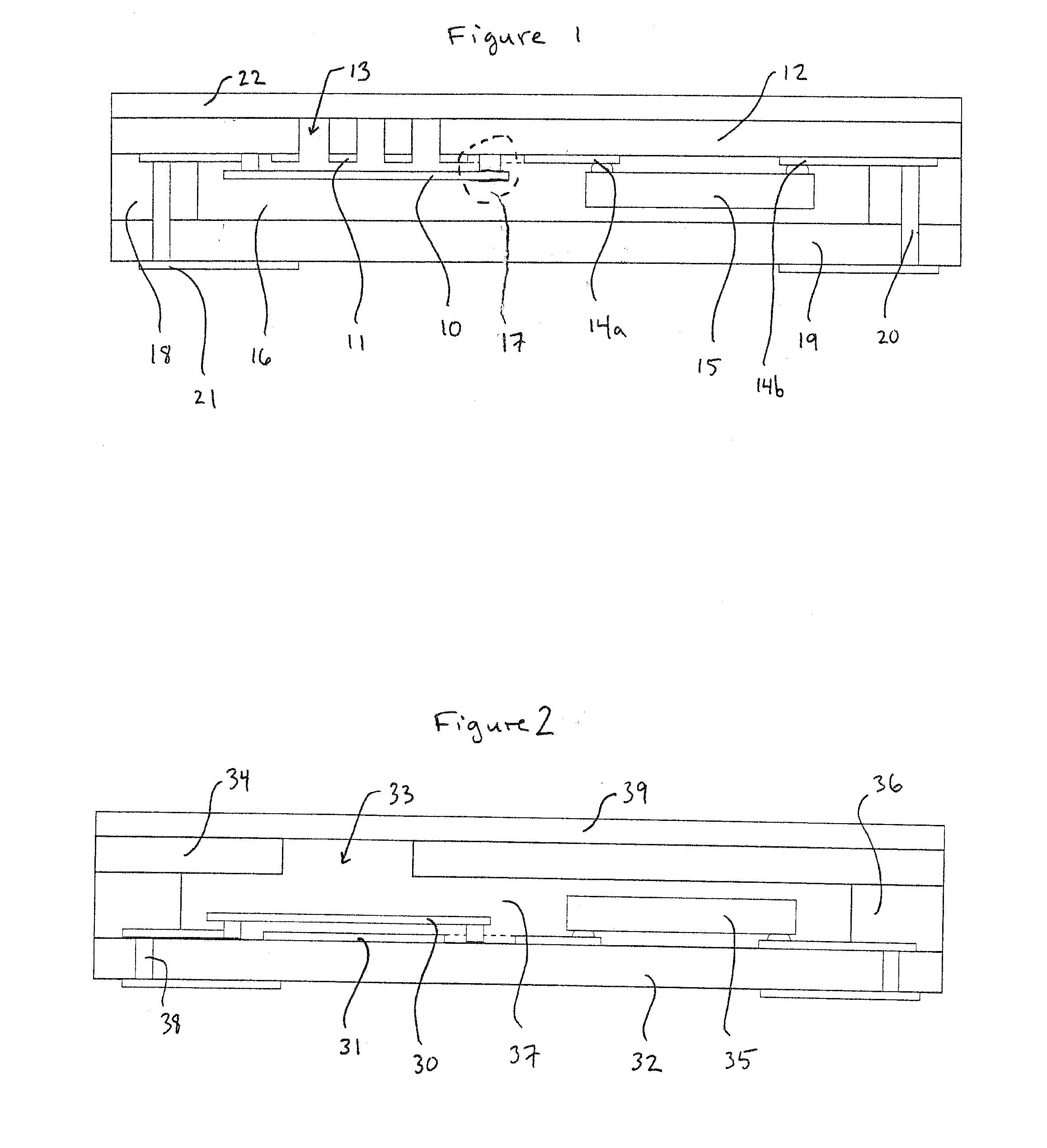
[0011]Embodiments of the subject invention relate to a method of fabricating a capacitive microphone. Embodiments also pertain to a capacitive microphone. In an embodiment, the subject capacitive microphone can use PCB-fabrication technology to realize a low-cost microphone integrated with the microphone package. FIG. 1 shows a cross-section of a specific embodiment of a capacitive microphone in accordance with the subject invention. The embodiment of FIG. 1 is a condenser microphone in which a surface micromachined diaphragm 10 is separated from a porous backplate 11 on the interior surface of a sheet of a PCB substrate 12. The diaphragm 10 can be positioned on the PCB substrate 12 such that a front surface of the diaphragm can be exposed to air passing through one or more apertures 13 formed in the PCB substrate 12. The microphone in FIG. 1 can also be an electret microphone by placing permanent electric charge on either the back plate or the diaphragm and creating an output signa...


PUM

PropertyMeasurementUnit
operating temperaturesaaaaaaaaaa
acoustic impedanceaaaaaaaaaa
acoustical impedanceaaaaaaaaaa

Abstract

A capacitive microphone and method of fabricating the same are provided. One or more holes can be formed in a first printed circuit board (PCB). A diaphragm can be surface micro-machined onto an interior surface of the first PCB at a region having the one or more holes. Interface electronics can also be interconnected to the interior surface of the PCB. One or more spacer PCBs can be attached to a second PCB to the first PCB, such that appropriate interconnections between interconnect vias are made. The second PCB and first PCB with spacers in between can be attached so as to create a cavity in which the diaphragm and interface electronics are located.

Description

CROSS-REFERENCE TO RELATED APPLICATION[0001]The present application claims the benefit of U.S. Application Ser. No. 60 / 926,307, filed Apr. 25, 2007, which is hereby incorporated by reference herein in its entirety, including any figures, tables, or drawings.BACKGROUND OF INVENTION[0002]Many consumer electronic products incorporate a microphone. As this is a high volume market, average selling price (ASP) is typically a key factor. The “Yole Silicon Microphone Market Report 2005” [1] projects the total silicon microphone market to be 2.75 M units and 221 M$ by 2008 with the major applications being mobile phones, PDAs, laptops, PCs, hearing aids, acoustic noise control and automotive crash detection. Many of these products use conventional electret condenser microphones (ECM) produced by a number of low cost suppliers. To date, one silicon micromachined microphone (Knowles acoustics SiSonic [2]) has been able to compete effectively in this market by meeting the performance, reliabili...

Claims


Application Information

Patent Timeline
Patent Type & Authority Applications(United States)
IPC IPC(8): H04R25/00H04R19/04H04R31/00
CPCH05K1/0272H04R19/04H04R2201/029H05K1/185H05K2201/10083H04R2201/02H04R31/003Y10T29/49005H04R1/04H05K1/16H04R2400/00Y10T29/49226H04R2231/00H01L2224/16225H04R31/006H05K3/46
Inventor SHEPLAK, MARKARNOLD, DAVID PATRICK
Owner UNIV OF FLORIDA RES FOUNDATION INC
Why Eureka
Try Eureka