Eureka AIR delivers breakthrough ideas for toughest innovation challenges, trusted by R&D personnel around the world.

Decoding method and system for real-time wireless channel estimation

a real-time wireless channel and channel estimation technology, applied in the field of error correction codes, can solve the problems of large computational capacity of computing ysup>2/sup>, and the receiver end may receive error messages, so as to avoid the problem of incorrect channel estimation and low log-max decoding performance

Inactive Publication Date: 2011-07-05
SUNPLUS TECH CO LTD
View PDF2 Cites 86 Cited by
  • Summary
  • Abstract
  • Description
  • Claims
  • Application Information

AI Technical Summary

Benefits of technology

[0020]An object of the present invention is to provide a decoding method and system for real-time wireless channel estimation, which can understand the channel condition (Â, {circumflex over (σ)}) when perform a Log-MAP decoding procedure is performed and therefore avoid the problems of incorrect channel estimation and low Log-MAX decoding performance.

Problems solved by technology

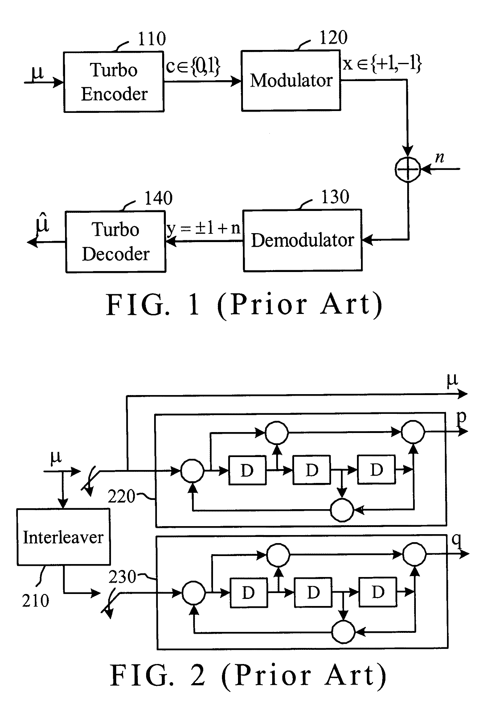
While a digital communication system transfers data, a receiving end may receive error messages because of non-predictable interferences or noises.
However, computing y2 consumes much computational capability.

Method used


Image

  • Decoding method and system for real-time wireless channel estimation
  • Decoding method and system for real-time wireless channel estimation
  • Decoding method and system for real-time wireless channel estimation

Examples


Embodiment Construction

[0044]FIG. 4 is a schematic diagram of a wireless transmission system in accordance with the invention. In FIG. 4, the wireless transmission system includes a turbo encoder 410, a modulator 420, a demodulator 430 and a turbo decoder 440, in which Gc indicates a wireless channel gains, n indicates an additive white Gaussian noise (AWGN) existed in the wireless channel, Ga indicates a system gain in a receiving system before the turbo decoder, and y indicates a receiving signal. The gain Gc is a constant in a code block and independent to each other in different code blocks. The AWGN noise n is Gaussian distribution with zero mean and variance σc2. The received signal y can be expressed by the following equation:

yi=GaGc√{square root over (Es)}xi+Gan=Axi+n′,

where the amplitude A=GaGc√{square root over (Es)}, and the AWGN noise n′ is Gaussian distribution with zero mean and equivalent variance σ2, where σ2=Ga2Gc2. Therefore, the effective SNR is given by:

[0045]SNRr=Gc2⁢Esσc2,

and an eff...


PUM


Abstract

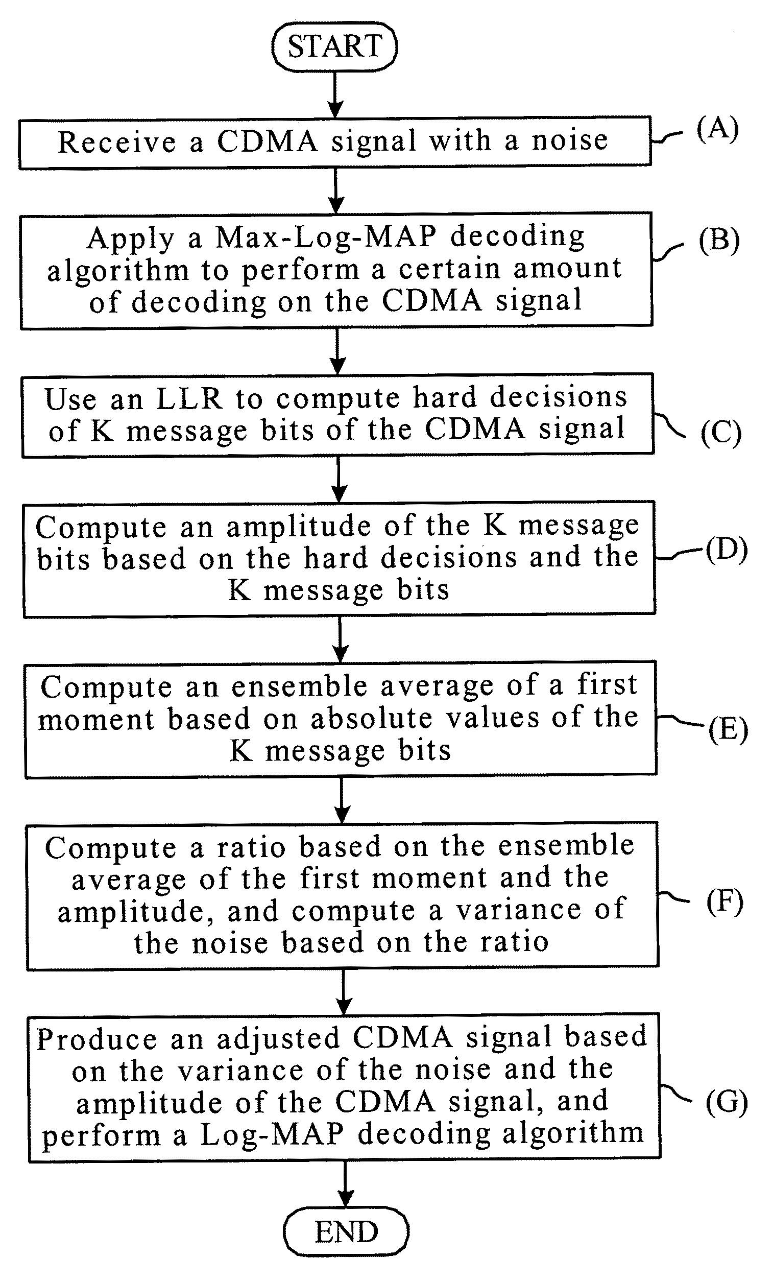
A decoding method and system for real-time wireless channel estimation, which decodes a received signal with a noise. The received signal is coded by a concatenation code. At first, the received signal is performed a certain amount of decoding by a Max-Log-MAP decoding procedure. Next, an estimated amplitude of the received signal and an estimated variance of a noise are computed. Then, the received signal is adjusted in accordance with the estimated amplitude and the estimated variance to thereby produce an adjusted received signal. Finally, the adjusted received signal is decoded by a Log-Map decoding procedure.

Description

BACKGROUND OF THE INVENTION[0001]1. Field of the Invention[0002]The present invention relates to the technical field of error correcting codes (ECCs) and, more particularly, to a decoding method and system for real-time wireless channel estimation.[0003]2. Description of Related Art[0004]While a digital communication system transfers data, a receiving end may receive error messages because of non-predictable interferences or noises. Therefore, a channel coding is used to effectively reduce the bit error rate, without raising the transmission power, which typically occupies partial bandwidth for transmission but ensures that the bit error rate is controlled in an acceptable range. In recent years, the data transmission is required day by day. For a future data transmission, the coverage becomes wider and the transmission rate becomes faster. Accordingly, the channel coding is considered as an important part in a wireless transmission system design.[0005]Turbo codes are an essential b...

Claims


Application Information

Patent Timeline
Patent Type & Authority Patents(United States)
IPC IPC(8): H04L27/06H03K9/00
CPCH03M13/2957H03M13/3905H03M13/6337H03M13/658H04L1/005H04L1/0055H04L1/0066H04L1/208H04L25/03171H04B1/69
Inventor SHIEH, SHIN-LINCHEN, PO-NINGHAN, YUNG-HSIANG
Owner SUNPLUS TECH CO LTD
Why Eureka
Eureka Blog
Learn More