Intake air sound generation device

a generation device and air technology, applied in the direction of transducer diaphragms, instruments, combustion air/fuel air treatment, etc., can solve the problems of poor member strength, difficult to maintain, and difficult to vibrate the diaphragm, so as to improve the vibrating body's durability and increase the sound pressure of the intake air sound

Active Publication Date: 2011-07-12
MAHLE JAPAN LTD +1
View PDF43 Cites 31 Cited by
  • Summary
  • Abstract
  • Description
  • Claims
  • Application Information

AI Technical Summary

Benefits of technology

[0004]It is therefore an object of this invention to provide an intake air sound generation device with which the durability of a vibrating body can be improved and the sound pressure of an intake air sound can be increased.

Problems solved by technology

However, in the intake air sound generation device according to the prior art, the disc-shaped diaphragm is fixed by sandwiching an outer edge of the diaphragm between an introduction tube and the resonance tube, and therefore the diaphragm does not vibrate easily.
To ensure that the diaphragm vibrates easily, the diaphragm may be formed from rubber having a low modulus of elasticity, but this type of rubber diaphragm exhibits poor member strength as a vibrating body, and is therefore problematic in terms of lifespan and durability.

Method used


Image

  • Intake air sound generation device
  • Intake air sound generation device
  • Intake air sound generation device

Examples


first embodiment

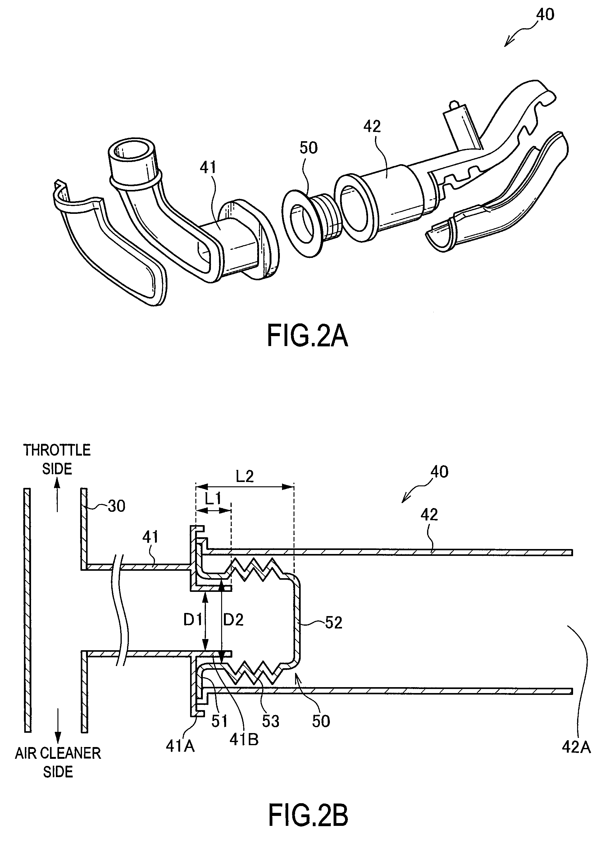
[0013]Referring to FIG. 1, FIGS. 2A and 2B, FIGS. 3A and 3B, and FIG. 4, this invention will be described.

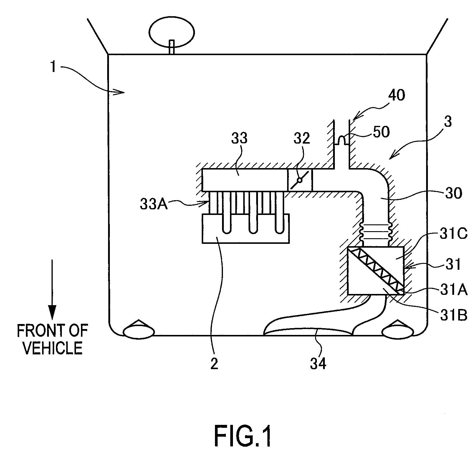
[0014]FIG. 1 shows the interior of an engine room 1 of a vehicle. The lower side of the drawing corresponds to the front of the vehicle.

[0015]A six-cylinder internal combustion engine 2 is disposed in the interior of the engine room 1.

[0016]The internal combustion engine 2 includes an intake system 3 that supplies fresh air taken in from the outside to each cylinder. The intake system 3 comprises an intake passage 30, an air cleaner 31, a throttle 32, and an intake manifold 33.

[0017]The intake passage 30 includes an intake port 34 located at the front of the vehicle for taking intake air in. The air cleaner 31 and the throttle 32 are disposed in the intake passage 30 in sequence from an upstream side. A downstream end of the intake passage 30 is connected to the intake manifold 33.

[0018]The air cleaner 31 is divided into a dust side 31B and a clean side 31C by a filter element 3...

second embodiment

[0055]Referring to FIGS. 5A and 5B and FIGS. 6A and 6B, this invention will be described.

[0056]The intake air sound generation device 40 according to the second embodiment has a substantially identical constitution to that of the first embodiment, but differs therefrom in a part of the constitution of the resonance tube 42.

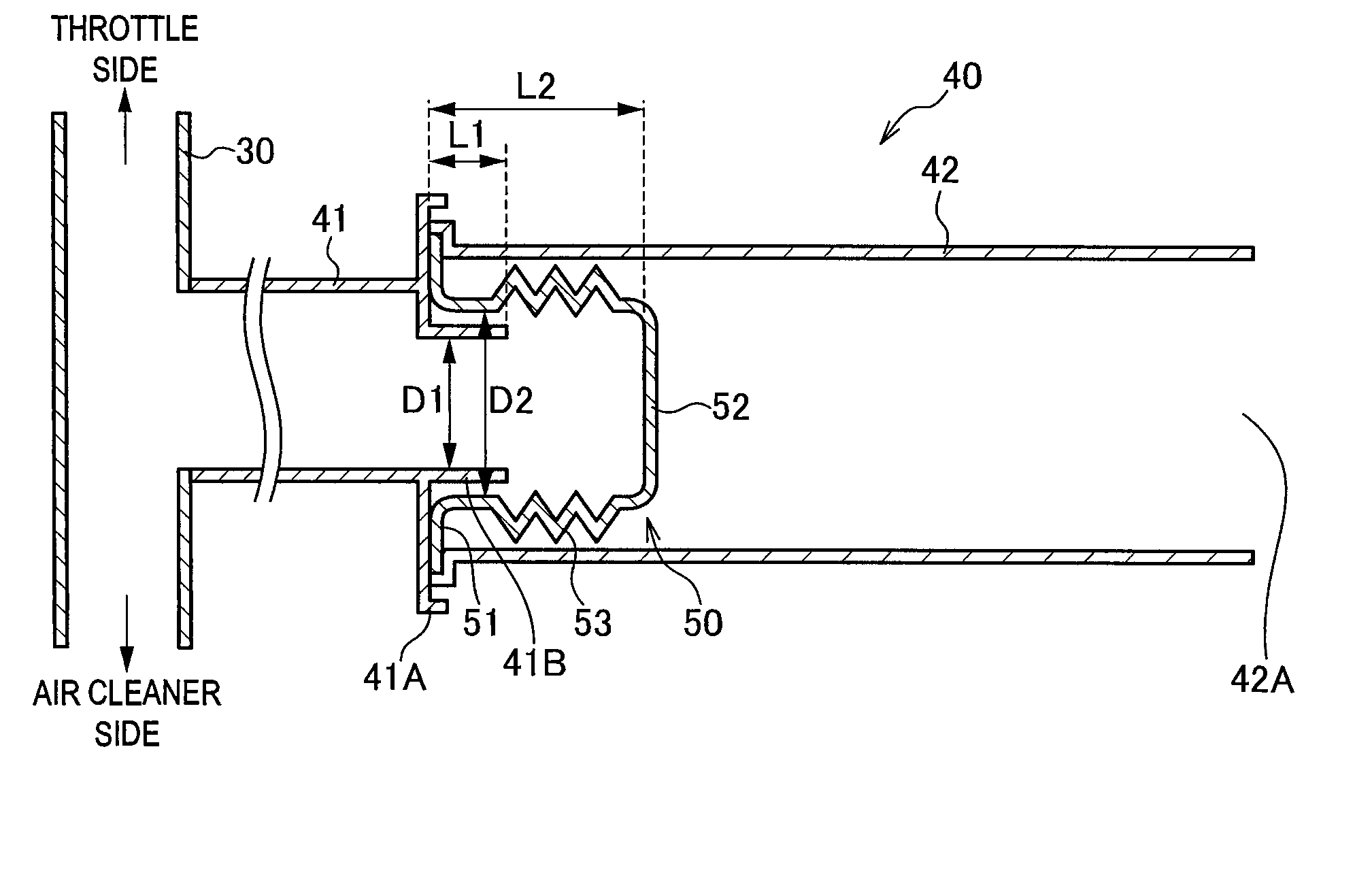
[0057]When a backfire occurs in the internal combustion engine 2, an extremely large pressure wave, i.e. a so-called excessive pulse, is formed in the interior of the intake system 3. When the excessive pulse is received by the vibration surface 52 of the vibrating body 50, the vibrating body 50 extends excessively in the axial direction, and as a result, the vibrating body 50 may be damaged.

[0058]Hence, in the intake air sound generation device 40 according to the second embodiment, a stopper 60 for restricting the position of the vibration surface 52 of the vibrating body 50 is formed in the interior of the resonance tube 42, as shown in FIG. 5A.

[0059]Referring ...


PUM


Abstract

An intake air sound generation device 40 for an internal combustion engine 2, comprises an introduction tube 41 which is connected to an intake passage 30 of the internal combustion engine 2 to introduce an intake pulse of an intake system, a vibrating body 50 which has a vibration surface 52 that is vibrated by the intake pulse and an accordion portion 53 that promotes vibration of the vibration surface 52, and is provided to cover one end of the introduction tube 41, and a resonance tube 42 which is connected to the introduction tube 41 via the vibrating body 50 and increases a sound pressure in a predetermined frequency band of an intake air sound generated by the vibration of the vibration surface 52. Thus, the sound pressure of the intake air sound at the predetermined frequency can be increased, and the durability of the vibrating body 50 can be improved.

Description

FIELD OF THE INVENTION[0001]This invention relates to an intake air sound generation device for an internal combustion engine.BACKGROUND OF THE INVENTION[0002]JP2007-170228A, published by the Japan Patent Office in 2007, discloses an internal combustion engine comprising an intake air sound generation device that causes a diaphragm to vibrate using an intake pulse and increases the sound pressure at a predetermined frequency of a resulting intake air sound using a resonance tube. According to the intake air sound generation device, a powerful intake air sound can be obtained within a vehicle cabin.SUMMARY OF THE INVENTION[0003]However, in the intake air sound generation device according to the prior art, the disc-shaped diaphragm is fixed by sandwiching an outer edge of the diaphragm between an introduction tube and the resonance tube, and therefore the diaphragm does not vibrate easily. To ensure that the diaphragm vibrates easily, the diaphragm may be formed from rubber having a l...

Claims


Application Information

Patent Timeline
Patent Type & Authority Patents(United States)
IPC IPC(8): G10K13/00F02M35/10F01N1/16F02M35/16
CPCF02M35/10295F02M35/10308F02M35/161F02M35/1222F02M35/1255F02M35/1272
Inventor YOKOYA, SHIGEHIROYAKABE, YOSHINORIHANADA, KYOUJIYOSHIDA, JUNJISHINADA, MASASHI
Owner MAHLE JAPAN LTD
Why Eureka
Try Eureka