End of a moldboard positioned proximate a milling drum

a moldboard and milling drum technology, applied in the field of machines, can solve the problems of poor bonding between the new layer and the milled surface, the recent milled surface is too dirty to resurface, and the sweeper is generally inefficient, so as to suppress the dust generated by milling and reduce friction, the effect of less aggregate accumulation

Inactive Publication Date: 2011-07-12
CATEPILLAR SARL +1
View PDF171 Cites 19 Cited by
  • Summary
  • Abstract
  • Description
  • Claims
  • Application Information

AI Technical Summary

Benefits of technology

[0005]The moldboard's end, by virtue of its proximity to the degradation drum, may restrict any loose aggregate from leaving the drum's proximity. Thus, the drum remains capable of directing the aggregate towards a conveyor for removal from the milling chamber. The moldboard may also direct aggregate towards the milling drum resulting in less aggregate accumulation and cleaner milled surfaces.
[0006]The moldboard may comprise a series of fluid nozzles. The nozzles may be located under the moldboard's end and may push the aggregate with a liquid toward the degradation drum and suppress dust generated from milling. The liquid may also be used to reduce friction, absorb heat, and clean the drum. Another series of nozzles located inside the milling chamber may clean the moldboard off and direct any aggregate back to the drum.

Problems solved by technology

However, some debris usually escapes underneath the bottom end of the moldboard leaving the recently milled surface too dirty to resurface.
Failure to clean the milled surface before resurfacing may result in poor bonding between the new layer and the milled surface.
Typically, a sweeper will follow the milling machine to remove the debris, but the sweeper is generally inefficient.

Method used


Image

  • End of a moldboard positioned proximate a milling drum
  • End of a moldboard positioned proximate a milling drum
  • End of a moldboard positioned proximate a milling drum

Examples


Embodiment Construction

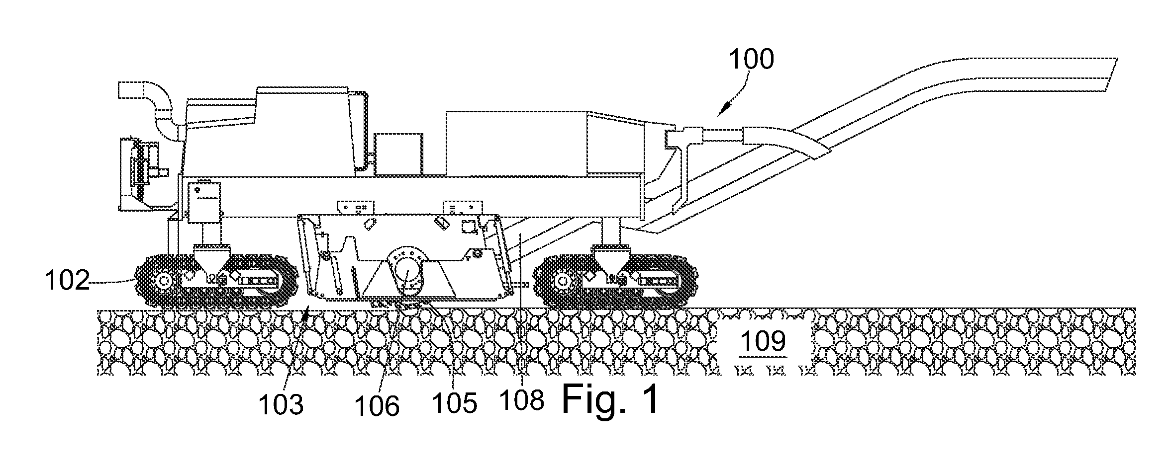
[0024]FIG. 1 discloses a milling machine 100 that may be used to remove asphalt from a paved surface 109. The current embodiment discloses the machine on tracks 102, but in other embodiments tires or other propulsion mechanisms may be used. A milling chamber 103 may be attached to the underside of the vehicle 100 and contain a milling drum 105, axle 106, and an opening for one end of a conveyor belt 108. The conveyor belt 108 may be adapted to remove debris from the milling chamber. The conveyor 108 may deposit the degraded surface into a truck (not shown). The truck may remove the degraded surface from the milling area.

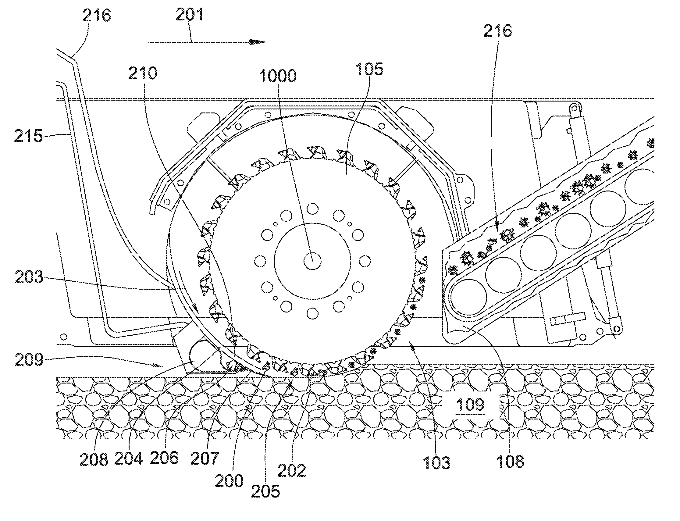
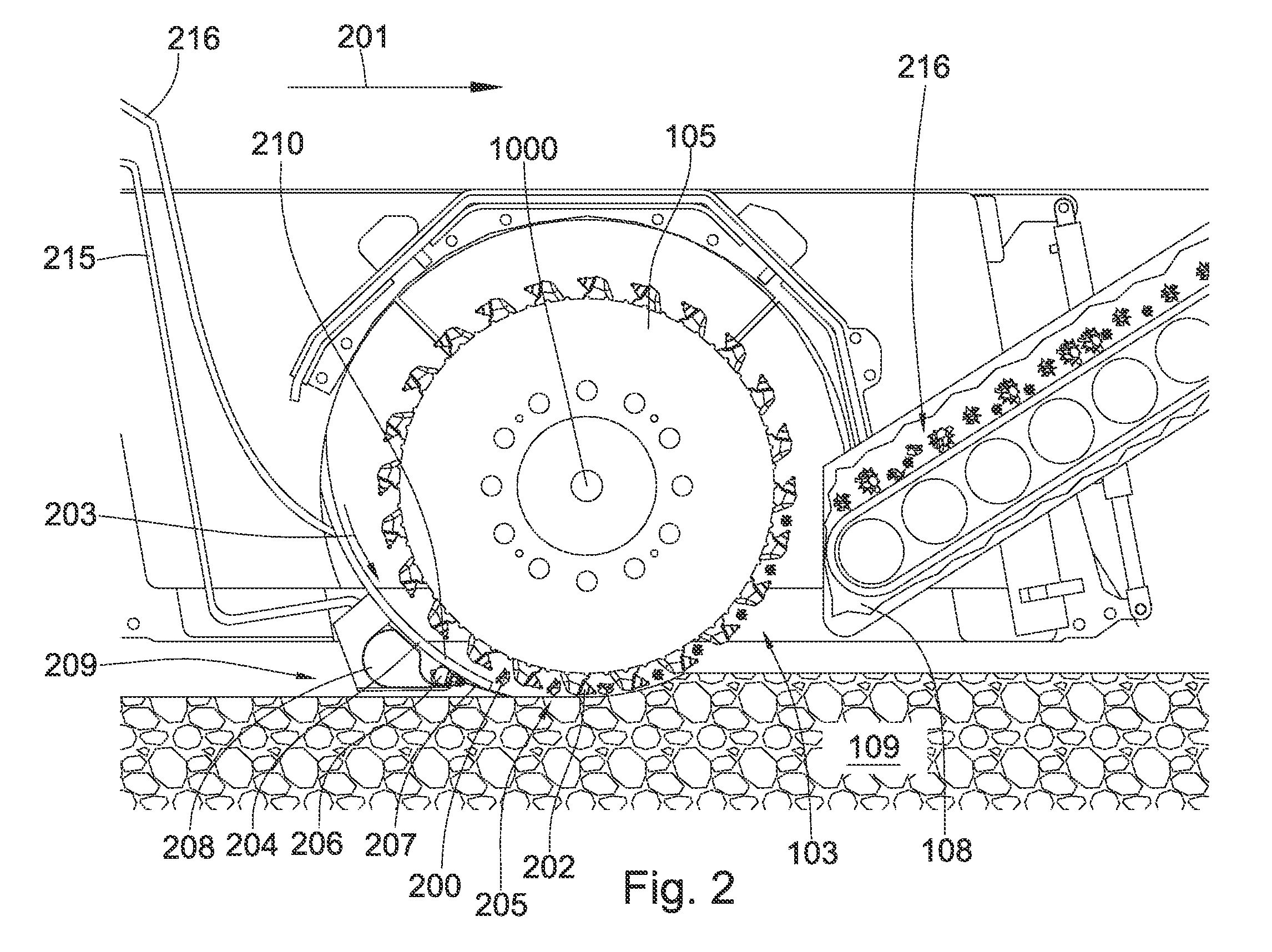
[0025]FIG. 2 discloses the milling chamber 103 and the conveyor belt 108. In this embodiment the milling machine travels to the right, as disclosed by arrow 201, and the drum 105 rotates counter-clockwise. An internal combustion engine (not shown) may be used to drive the milling drum. The picks 202 degrade the paved surface by rotating into the paved surface as the ...


PUM


Abstract

In one aspect of the present invention, the present invention is a system for removing aggregate from a paved surface. The system includes a motorized vehicle with a degradation drum that is connected to the underside of the vehicle. The degradation drum is enclosed by a milling chamber. The milling chamber is defined by having a plurality of plates, including a moldboard positioned rearward of the milling drum. The moldboard comprises an end that is disposed opposite the underside. The end comprises a section that is proximate the milling drum.

Description

CROSS REFERENCE TO RELATED APPLICATIONS[0001]This application is a continuation of U.S. patent application Ser. No. 12 / 888,876, filed Sep. 23, 2010, which is a continuation-in-part of U.S. patent application Ser. No. 12 / 145,409 filed Jun. 24, 2008 now U.S. Pat. No. 7,854,566; which was a continuation-in-part of U.S. patent application Ser. Nos. 11 / 566,151 filed Dec. 1, 2006 now U.S. Pat. No. 7,458,645; Ser. No. 11 / 668,390 filed Jan. 29, 2007 now U.S. Pat. No. 7,507,053; and Ser. No. 11 / 644,466 filed Dec. 21, 2006 now U.S. Pat. No. 7,596,975. All of these documents are herein incorporated by reference for all that they disclose.BACKGROUND OF THE INVENTION[0002]The present invention relates to machines that are used in road construction, such as a milling machine. These machines may remove a layer or layers of old or defective road surfaces to prepare for resurfacing. Typically, milling machines are equipped with a milling drum secured to the machine's underside. The drums are configu...

Claims


Application Information

Patent Timeline
Patent Type & Authority Patents(United States)
IPC IPC(8): E01C23/12
CPCE01C23/088E01C2301/50
Inventor HALL, DAVID R.JEPSON, JEFFMORRIS, THOMASNIELSON, JOSEPHCROCKETT, RONALD B.PETERSON, GARYWAHLQUIST, DAVID
Owner CATEPILLAR SARL
Why Eureka
Try Eureka