Quadrature frequency doubler with adjustable phase offset

a phase offset and quadrature frequency technology, applied in the field of quadrature frequency doublers with adjustable phase offset, can solve the problems of quadrature phase error, limiting circuit bandwidth, and consuming die space of tuned loads, and achieves small phase step, adequate range, and low average achievable sideband rejection

Active Publication Date: 2011-07-12
EDGEWATER WIRELESS SYST
View PDF1 Cites 15 Cited by
  • Summary
  • Abstract
  • Description
  • Claims
  • Application Information

AI Technical Summary

Benefits of technology

[0018]In accordance to a preferred embodiment, the frequency doubler of the present invention further comprises a phase shifter for further reducing phase errors between the two quadrature signals of frequency 2ω.

Problems solved by technology

However, many state-of-the-art frequency doubling circuits introduce amplitude mismatch and quadrature phase offset between the quadrature signals.
Unfortunately, tuned loads consume die space and limit circuit bandwidth.
This unbalanced loading leads to quadrature phase error.
However, the circuit in FIG. 1b introduces considerable amplitude imbalance when mixer non-linearities are considered.
The result is that the amplitude of the I output will be lower than the amplitude of the Q output, an unacceptable imbalance when used in a doubler design to provide the LO in an image reject mixer.
This implies drive levels too low to be useful for driving mixer LO ports, and subsequently a high noise floor.
In practice large signal effects in the presence of this nonlinearity will cause mixer imbalances resulting in slight phase offsets.
If the topology in FIG. 1b is used, the outputs will exhibit amplitude imbalance proportional to the drive level at the polyphase filter input owing to the aforementioned mixer nonlinearities.
However, this approach presupposes a wide dynamic range predistortion circuit.
Process variations will cause such a circuit to contribute to output phase and amplitude imbalance.
Additional, although amplitude mismatch is a major source of error, phase offset between the quadrature signals represents another source of error.

Method used


Image

  • Quadrature frequency doubler with adjustable phase offset
  • Quadrature frequency doubler with adjustable phase offset
  • Quadrature frequency doubler with adjustable phase offset

Examples


Embodiment Construction

[0029]In the following detailed description, numerous specific details are set forth in order to provide a thorough understanding of the invention. However, it will be understood by those skilled in the art that the present invention may be practiced without these specific details. In other instances, well-known methods, procedures, components and circuits have not been described in detail so as not to obscure the present invention.

[0030]Essentially, the present invention attempts to alleviate problems of the prior art in a manner with little sensitivity to manufacturing deviations, by providing a frequency doubling circuit and method for obtaining quadrature signals, in which inputs of substantially same phase offset are provided to mixers of the provided circuits or, equivalently, are mixed together within the provided method.

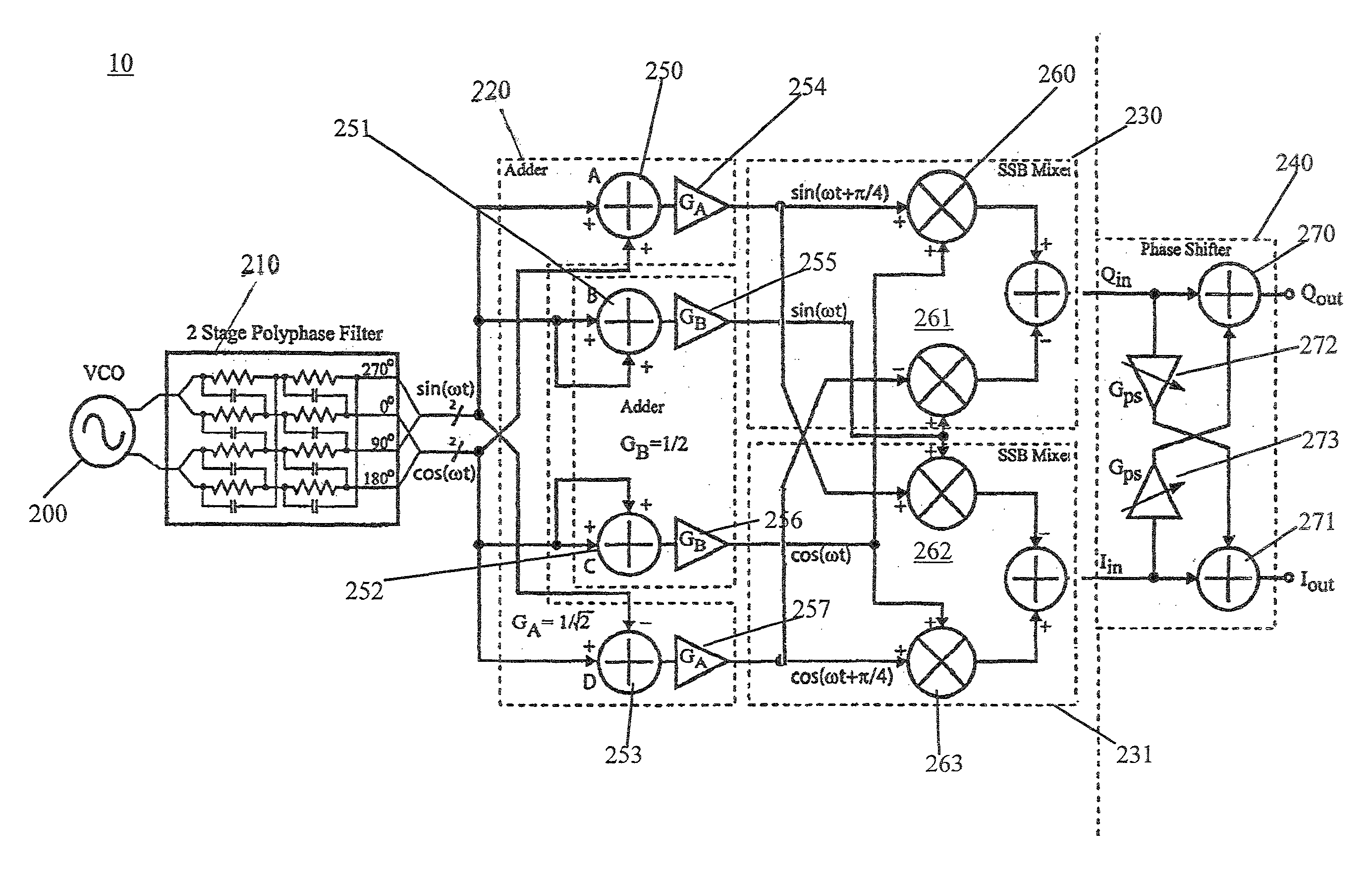
[0031]FIG. 4 illustrates a representative embodiment of a frequency doubler 10 according to the present invention. Frequency doubler 10 comprises a voltage c...


PUM


Abstract

The present invention provides an improved frequency doubling circuit, with adjustable phase offset. Briefly, rather than using the traditional equations cos (2ωt)=cos 2(ωt)−sin 2(ωt) and sin(2ωt)=2 sin(ωt)cos(ωt), the quadrature output signals are generated utilizing mixers, each having two input signals, separated in phase by the same offset. This minimizes the effects of the non-linearities introduced by the mixer, which therefore reduces amplitude mismatch between the quadrature signals. Also, the phase offset of the quadrature output signals can be tuned and calibrated using a phase shifting circuit. This phase shifting circuit realizes a tuning range of approximately 5° in programmable steps. This combination of circuits can be used to minimize the amplitude mismatch and phase errors, thereby reducing the amplitude of and interference caused by transmission of the image frequency to the receivers input.

Description

CROSS-REFERENCE TO RELATED APPLICATIONS[0001]This application claims benefit from U.S. Provisional Patent Application Ser. No. 60 / 821,252 filed on Aug. 2, 2006, the entire content of which is incorporated herein by reference.BACKGROUND OF THE INVENTION[0002]Full-duplex RF front-ends in WLAN networks require careful design to limit receive desensitization due to transmit noise and transmit error vector magnitude (EVM) degradation caused by receiver local oscillator (LO) leakage to the transmit path. In addition, frequency pulling is a concern in full duplex systems where receive and transmit voltage-controlled oscillators (VCOs) must operate simultaneously and be close in frequency.[0003]As a consequence, such full-duplex systems and many other applications, require two driving signals, typically referred to as I and Q or quadrature signals, having the same frequency and having their phases in quadrature with each other, i.e. presenting a relative phase offset of 90°. It is important...

Claims


Application Information

Patent Timeline
Patent Type & Authority Patents(United States)
IPC IPC(8): H03B19/00
CPCH03B19/14H03B2200/0036H03B2200/0078
Inventor LEIFSO, CURTIS
Owner EDGEWATER WIRELESS SYST
Why Eureka
Try Eureka