
Device for keeping warm slabs emerging from a continuous casting installation

a technology of continuous casting installation and device, which is applied in the direction of lighting and heating apparatus, furniture, charge manipulation, etc., can solve the problems of large loss of steel energy used for melting in the continuous casting installation, cost-driving factors in steel mills and continuous casting installations, etc., and achieve the effect of less heat loss

Inactive Publication Date: 2011-07-19
SMS DEMAG AG
View PDF7 Cites 1 Cited by
  • Summary
  • Abstract
  • Description
  • Claims
  • Application Information

AI Technical Summary

Benefits of technology

[0009]It is an object of the invention to keep the slab as hot as possible by optimizing the balance of energy of the process between the continuous casting installation and the hot rolling mill so that the average caloric temperature is as high as possible. In so doing, as much heat as possible should be preserved up to the insertion of the slab into the rolling mill in order to minimize costs for reheating.
[0011]A strand continuously exits from a continuous casting installation in the shape of a slab, for example, and is then separated into individual slabs or slab segments. The transporting is generally carried out on a roller table directly adjoining the roller guide of the strand guide. This also applies to the further transport when, for example, inline rolling is carried out downstream. The arrangement according to the invention is useful for preventing interim temperature losses.
[0013]Alternatively, it may be very advantageous to use insulating boxes directly as an intermediate storage provided the buffer period does not exceed several hours.
[0017]Further, a transporting of packages, that is, stacked slabs, is also possible with the insulating boxes. An advantage of transporting in packages is that the furnace of the rolling mill can be charged with a plurality of products simultaneously. The furnace need only be opened once for a plurality of products and need not be opened separately for each product so that appreciably less heat is lost.

Problems solved by technology

One of the greatest cost-driving factors in steel mills and continuous casting installations is the energy that is used, for the most part, to generate heat.
The great amount of energy used for melting is lost to the steel in the continuous casting installation for the sake of bringing about solidification.

Method used


Image

  • Device for keeping warm slabs emerging from a continuous casting installation
  • Device for keeping warm slabs emerging from a continuous casting installation
  • Device for keeping warm slabs emerging from a continuous casting installation

Examples


Embodiment Construction

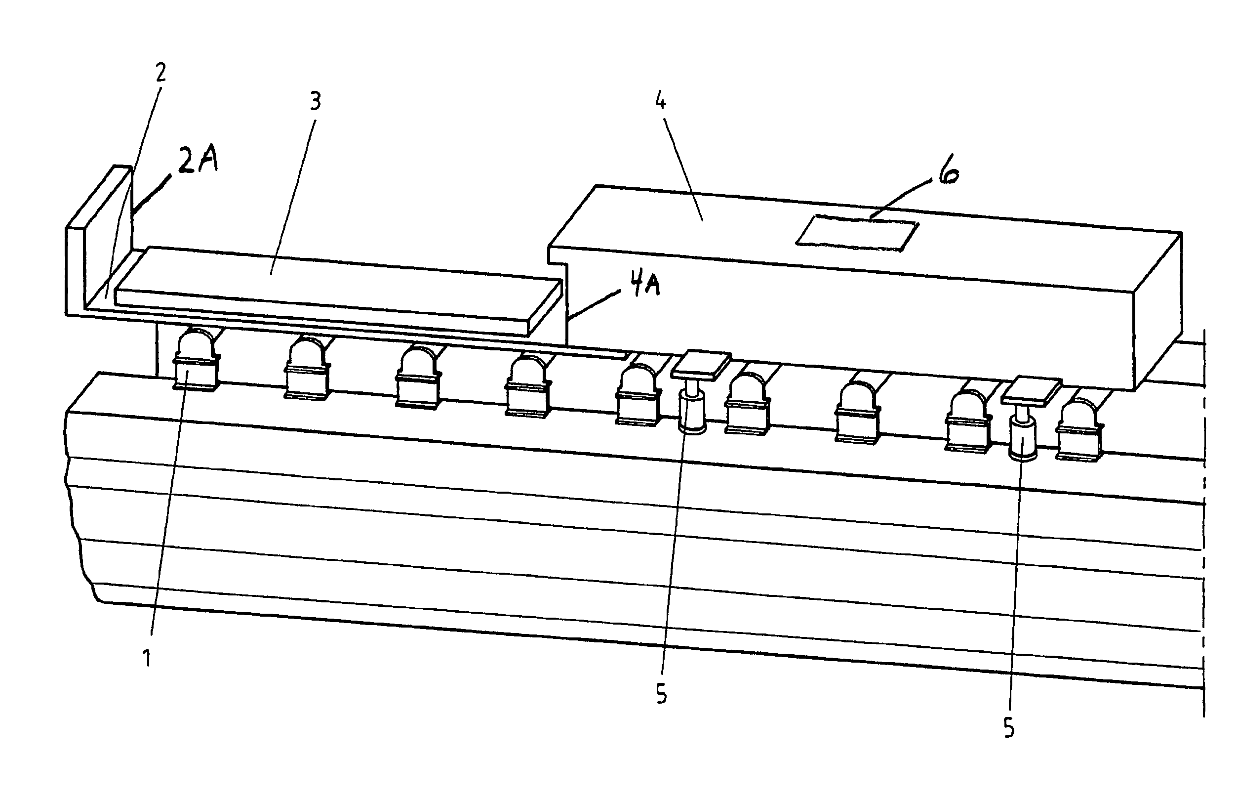
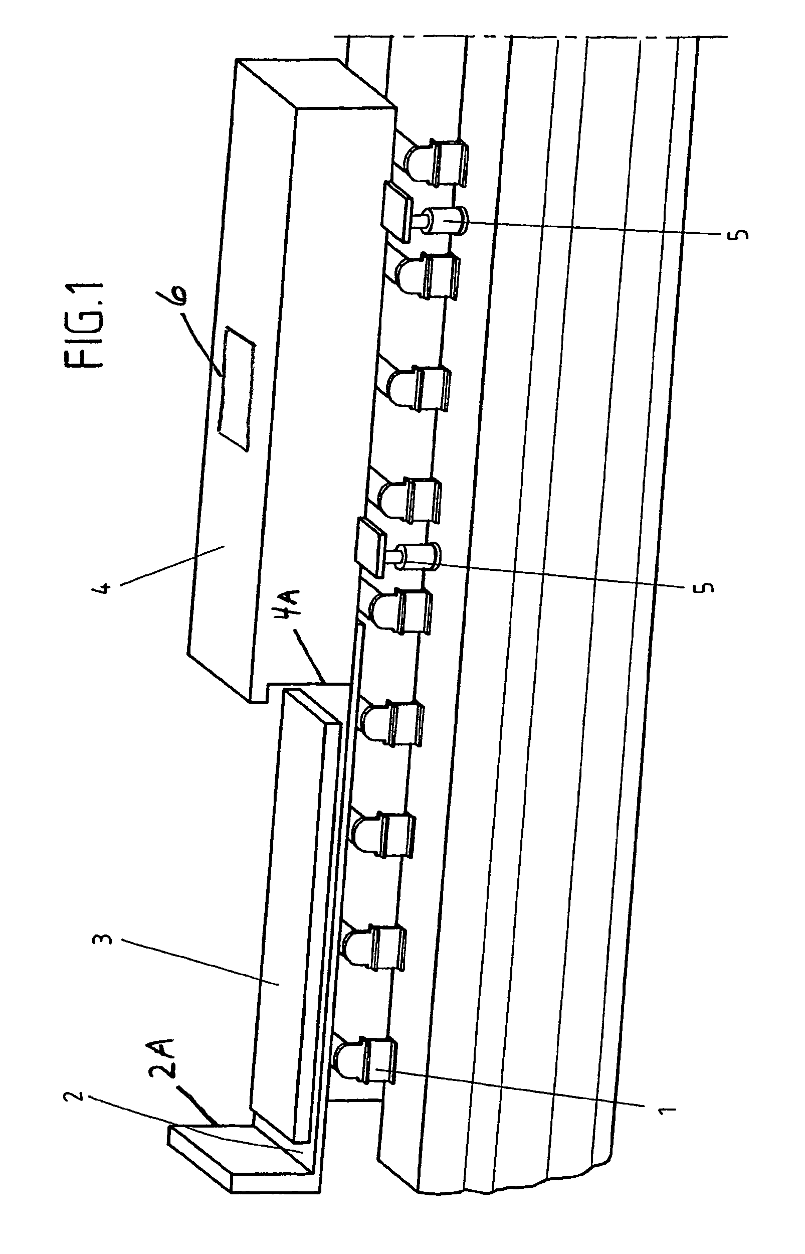
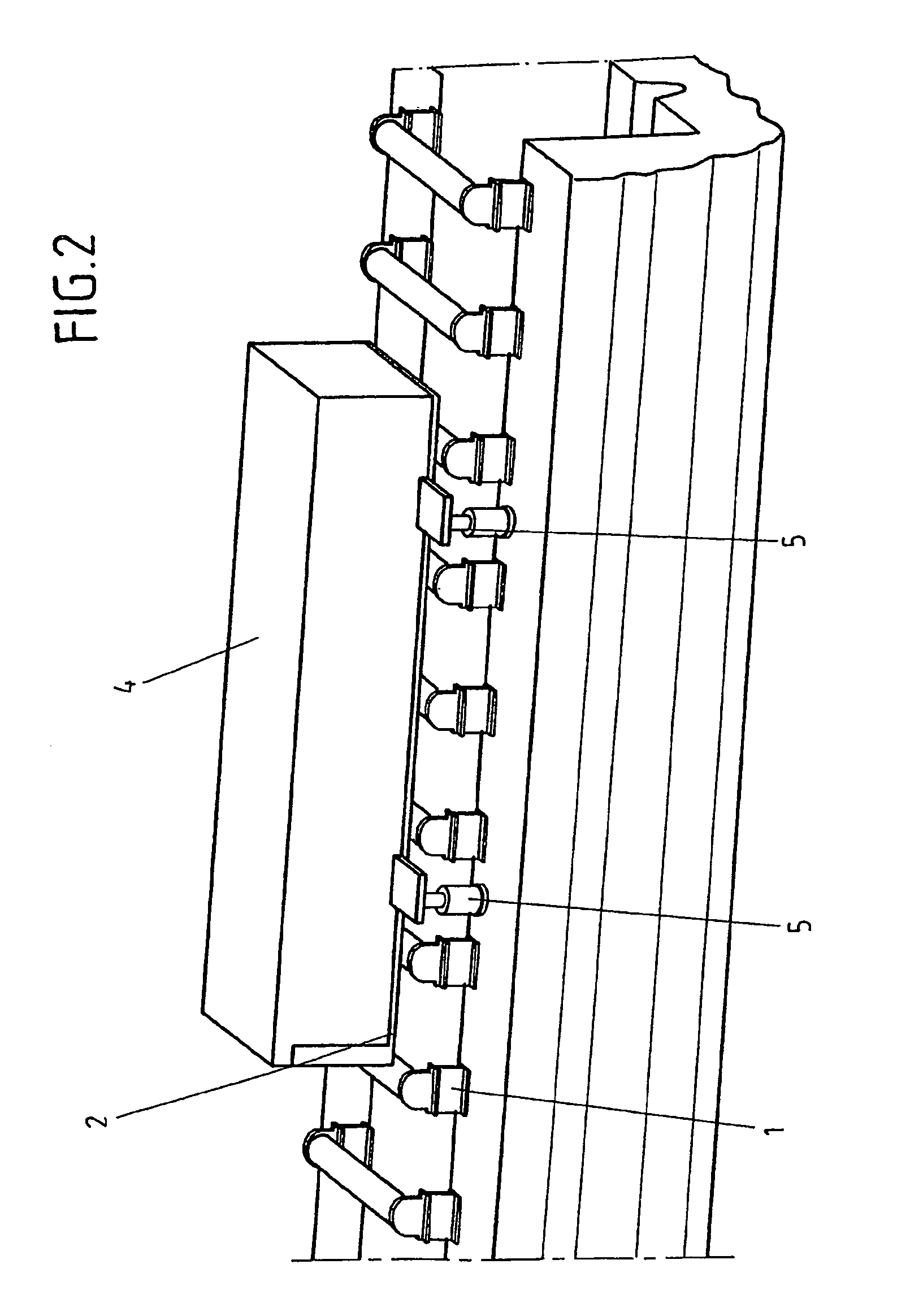
[0022]An arrangement according to one embodiment of the invention is shown in FIG. 1 for maintaining the warmth of slabs, which exit from a continuous casting installation, comprises an insulated supporting part 2 which receives a slab 3 and can be conveyed on a roller table 1 and an insulating box 4 in which the supporting part 2 can be inserted. For this purpose, the insulating box 4 is tunnel-shaped, that is, open in longitudinal direction and, therefore, in direction of the roller table 1, while the other side is closed. Accordingly, the supporting part 2 which has at one end a terminating wall 2A whose dimensions correspond to the clearance opening 4A of the insulating box 4 can be inserted into the insulating box 4 and closes it from this side as shown in FIG. 2.

[0023]In the embodiment form shown in the drawings, a lifting device is provided for the insulating box 4 in order to allow the supporting part, to be pushed or inserted into the insulating box 4. This lifting device c...


PUM

PropertyMeasurementUnit
Electrical resistanceaaaaaaaaaa
Areaaaaaaaaaaa
Thermal propertiesaaaaaaaaaa

Abstract

An arrangement for maintaining the warmth of slabs which exit from a continuous casting installation and which can be transported on a roller table for further processing. In order to optimize the thermal balance between the continuous casting installation and the hot rolling mill, a supporting part is provided for receiving a slab, which supporting part can be placed on the roller table and transported thereon, and an insulating box which can be placed upon the supporting part and which substantially encloses the latter.

Description

PRIORITY CLAIM[0001]This is a U.S. national stage of application No. PCT / DE2007 / 001462, filed on 13 Aug. 2007. Priority is claimed on the following applications: Country: Germany, Application No.: 10 2006 041 150.1, Filed: 1 Sep. 2006; Country: Germany, Application No.: 10 2007 016 100.1, Filed: 27 Mar. 2007, the contents of which are incorporated here by reference.BACKGROUND OF THE INVENTION[0002]1. Field of the Invention[0003]The invention is directed to an arrangement for maintaining the warmth of slabs which exit from a continuous casting installation and which can be transported on a roller table for further processing.[0004]2. Description of the Prior Art[0005]One of the greatest cost-driving factors in steel mills and continuous casting installations is the energy that is used, for the most part, to generate heat.[0006]The great amount of energy used for melting is lost to the steel in the continuous casting installation for the sake of bringing about solidification. Followin...

Claims


Application Information

Patent Timeline
IPC IPC(8): B22D45/00
CPCB21B45/008B22D11/1213F27D3/0024B21B45/004B21B45/0203Y02P70/10B22D11/128F27D3/12
Inventor FEST, THOMASHOVESTADT, ERICHMOSSNER, WOLFGANG
Owner SMS DEMAG AG
Learn More