Liquid color injection pressure booster pump and pumping methods

a pressure booster pump and liquid color technology, applied in the direction of positive displacement liquid engine, pump components, piston pump, etc., can solve the problems of low pump efficiency, low cost, and difficulty in achieving the effect of low cost, no expensive parts, and low cos

Inactive Publication Date: 2011-07-19
MAGUIRE STEPHEN B
View PDF52 Cites 47 Cited by
  • Summary
  • Abstract
  • Description
  • Claims
  • Application Information

AI Technical Summary

Benefits of technology

[0014]The liquid color injection pressure booster pump of this invention solves the problem described above in two ways. First, the liquid color injection pressure booster pump in accordance with the invention is a very low cost device, having no expensive parts. A very low cost pressure seal is the only wear item in the pump, should the liquid color attack this part.
[0015]Secondly, the liquid color injection pressure booster pump of this invention utilizes a design that tends to keep the liquid away from the seal, thereby extending the life of even the seal, which, as noted above, is the only wear item. The liquid color injection booster pump of this invention is air actuated and does not require a drive motor.

Problems solved by technology

When colors are changed, some of the coloring agent, whether the agent be liquid color or solid color pellets, is always lost due to the time required to purge the old color from the process machine and to introduce the new coloring agent at full strength.
A problem with this approach, namely introducing liquid color into the extrusion screw barrel downstream of the throat, is that pressure in the extrusion screw barrel must be overcome by the metering pump delivering the liquid color.
Previously, pumps have been used with limited success to supply liquid color directly into the barrel of an extruder screw.
This is a disadvantage because many color pigments are abrasive.
White color pigment, which is titanium dioxide, is extremely abrasive and is similar to finely ground stone.
Using a gear pump to feed color pigment as a component of liquid color, particularly white liquid color with its very fine particles of titanium dioxide, wears the gears in a gear pump to an unacceptable point in a very, very short time.
A further disadvantage of gear pumps is that they are very expensive.
Processors simply have not embraced the introduction of liquid color into the barrels of extruder screws or injection molding machines at positions removed from the throat.

Method used


Image

  • Liquid color injection pressure booster pump and pumping methods
  • Liquid color injection pressure booster pump and pumping methods
  • Liquid color injection pressure booster pump and pumping methods

Examples


Embodiment Construction

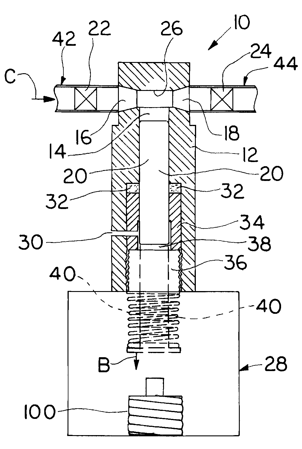
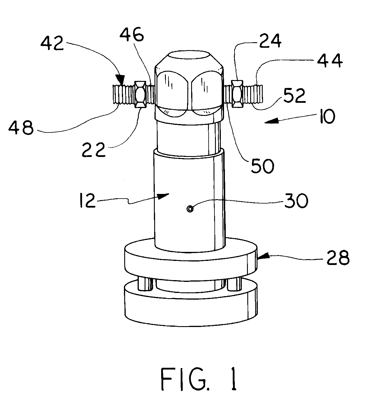
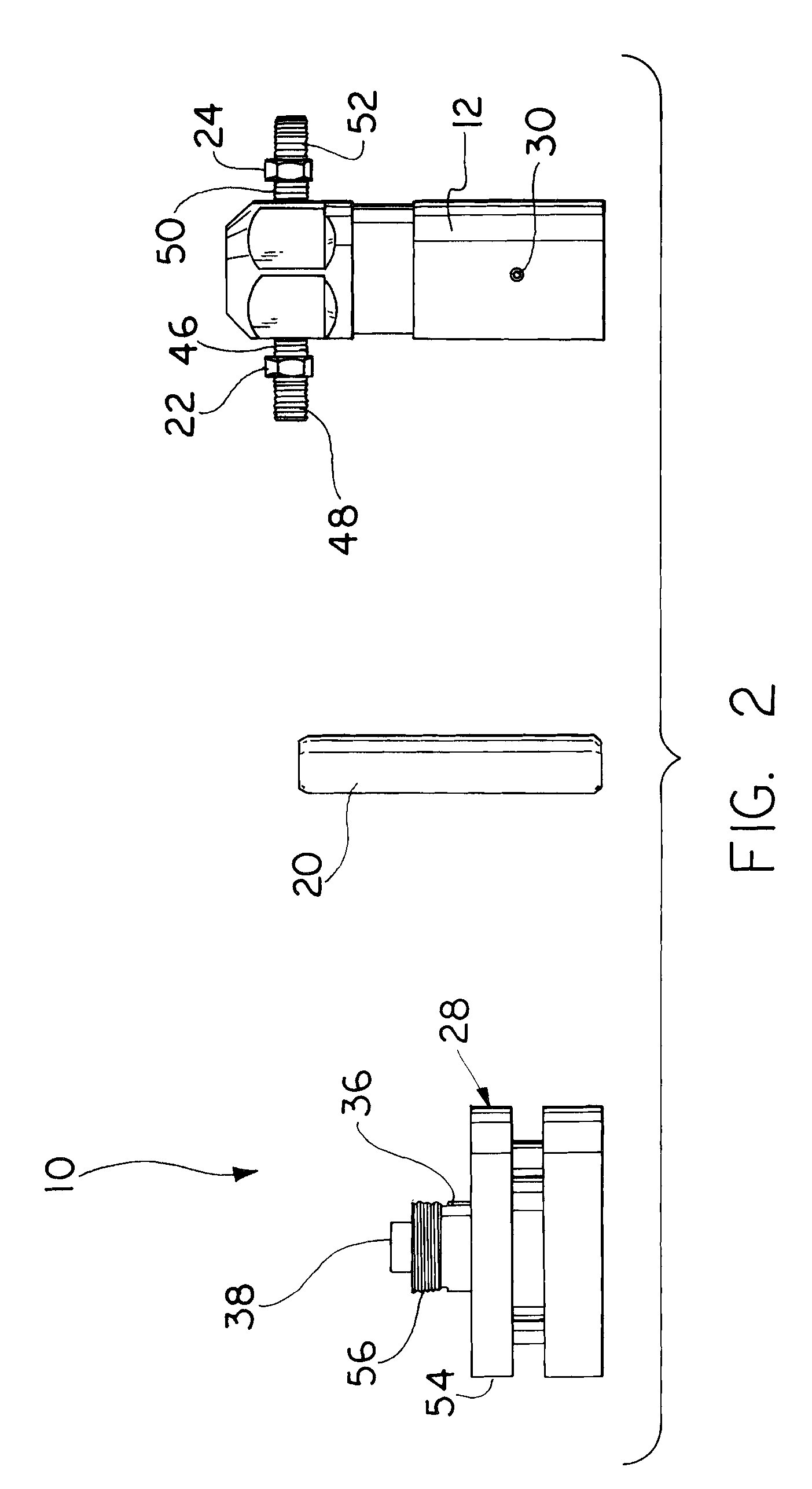
[0037]Referring to the drawings in general and to FIG. 1 in particular, a liquid color injection pressure booster pump in accordance with the preferred embodiment of the invention is designated generally 10 and includes a housing designated generally 12 that is connected to an air cylinder / solenoid combination designated generally 28. A vent aperture 30 is provided in housing 12, as explained in more detail below.

[0038]An inlet passageway to liquid color injection pressure booster pump 10, for flow of liquid color therethrough, is designated generally 42 in FIG. 1. Inlet passageway 42 may be defined by a first threaded pipe nipple 46 and a second threaded pipe nipple 48, both shown in FIG. 1, where inlet check valve 22 is positioned between and in threaded engagement with first and second threaded pipe nipples 46, 48. Pipe nipple 46 may threadedly engage a first bore designated 14, which is not shown in FIG. 1, but is shown in FIGS. 3 and 4 as described in more detail below, which b...


PUM


Abstract

A pump for boosting pressure of liquid color for injection into plastic resin in molding or extrusion apparatus includes a housing having a first bore extending in a first direction and second and third bores extending through the housing and communicating with the first bore proximate a first end of the first bore with the first end of the first bore being blind. The pump further includes an inlet check valve connectable to the second bore for permitting liquid flow through the second bore into the first bore. Further included is an outlet check valve connective to the third bore for permitting liquid flow out of the first bore through the third bore. A member is reciprocally axially movable within the first bore. A solenoid applies air pulses to the end of the first member facing oppositely from the blind end of the first bore.

Description

BACKGROUND OF THE INVENTION[0001]1. Field of the Invention[0002]This invention relates generally to processing of resin material for fabrication into finished articles and more particularly to methods and apparatus for furnishing liquid color material used to impart a desired color to the finished plastic part.[0003]2. Description of the Prior Art[0004]When liquid color is used to impart a desired color to finished parts produced by molding or extrusion, the liquid color is normally introduced into the process at the throat of the process machine, along with the flow of plastic resin or pellets. In this context the “throat” of the process machine refers to the position at which the plastic resin is initially introduced into a barrel surrounding one or more extrusion screws, if the process machine is a extruder, or the position at which the plastic resin is initially introduced into the screw barrel housing, if the process machine is an injection molding press.[0005]At the throat of ...

Claims


Application Information

Patent Timeline
Patent Type & Authority Patents(United States)
IPC IPC(8): F04B17/00
CPCF04B9/127F04B53/16F04B15/02F04B53/14
Inventor MAGUIRE, STEPHEN B.
Owner MAGUIRE STEPHEN B
Why Eureka
Try Eureka