Coherent frequency modulated continuous wave radar

a coherent technology, applied in the field of frequency modulated continuous wave (fmcw) radar, can solve the problems of limiting the development of coherent fmcw radar systems, radars are not able to measure the difference in phase between transmitted and returned signals, and the range resolution of fmcw radars is seriously degraded, so as to achieve the effect of improving range sensitivity

Active Publication Date: 2011-07-19
QINETIQ LTD
View PDF27 Cites 24 Cited by
  • Summary
  • Abstract
  • Description
  • Claims
  • Application Information

AI Technical Summary

Benefits of technology

[0012]Accordingly, it is an object of the present invention to provide a coherent FMCW radar, and a method of coherent radar operation, that mitigates at least some of above described disadvantages. It is a further object of the invention to provide a coherent FMCW radar having improved range sensitivity and / or that can operate at frequencies greater than around 20 GHz.

Problems solved by technology

Although it is trivial to produce a high quality linear voltage variation (e.g. a triangular or saw-tooth waveform), conversion to the corresponding frequency variation by the VCO often results in the introduction of significant non-linearities that seriously degrade the range resolution of the FMCW radar.
In other words, the radars only output information related to the frequency shift between the transmitted and returned signals; the radars are not able to measure the difference in phase between transmitted and returned signals.
Despite the clear benefits of coherent operation, the requirement to not only control the linearity of the frequency sweep but to also control the absolute frequency of each sweep has limited the development of coherent FMCW radar systems.
Although DDS allows the production of repeatable waveforms, it can only provide such waveforms at frequencies up to around 1 GHz.
The up-conversion technique involves a local oscillator which will drift with frequency and does not lend itself to coherent operation.
The phase locked loop technique can provide coherent operation at frequencies below 20 GHz but the phase noise of the transmitted signal is very poor resulting in poor radar sensitivity.

Method used


Image

  • Coherent frequency modulated continuous wave radar
  • Coherent frequency modulated continuous wave radar
  • Coherent frequency modulated continuous wave radar

Examples


Embodiment Construction

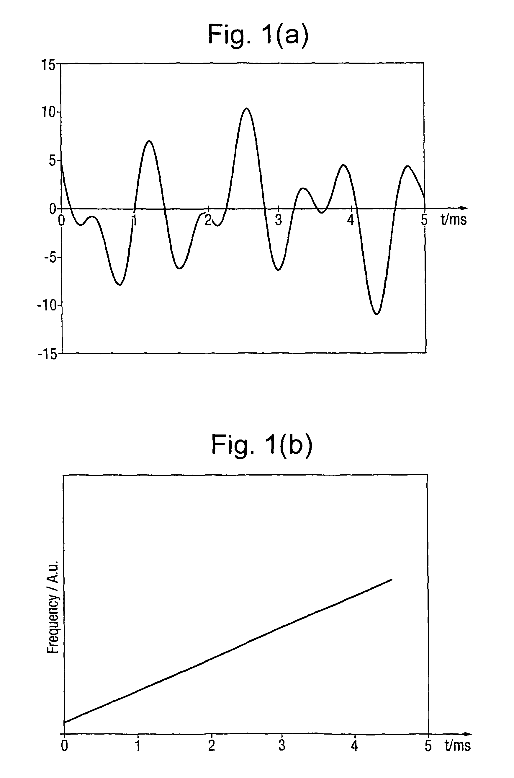
[0092]Referring to FIGS. 1(a) and 1(b), the underlying principle of an FMCW radar that is linearly swept in frequency is illustrated. FIG. 1a illustrates the amplitude of the received signal (after down-conversion) as a function of time for an FMCW radar whilst FIG. 1b illustrates the variation in frequency of the radar output as a function of time.

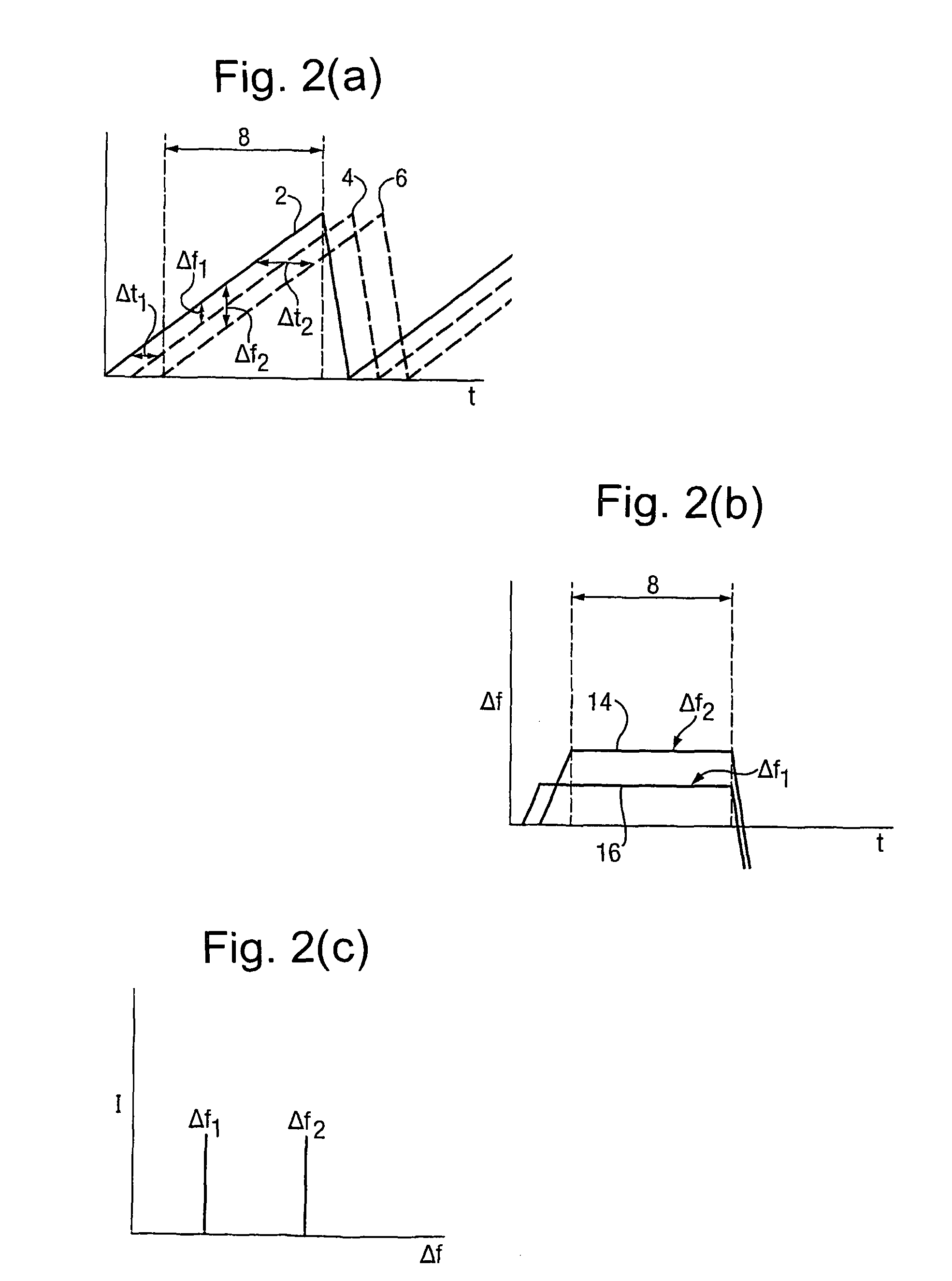
[0093]FIGS. 2(a), 2(b) and 2(c) illustrate how range information can be determined using an FMCW radar. Line 2 of FIG. 2a shows the saw-tooth frequency variation of the transmitted signal of the radar, line 4 shows the frequency variation with time of a signal returned from a target at a first distance d1 from the radar and line 6 shows the frequency variation with time of a signal returned from a second target at a second distance d2 from the radar. In this case, the target at d2 is approximately twice the distance from the radar as the target at d1.

[0094]It can be seen that line 4 is time shifted (i.e. delayed) from line 2 by Δt1, whils...


PUM


Abstract

A frequency modulated continuous wave (FMCW) radar is described. The radar includes a first discriminator for receiving a portion of the swept frequency signal generated by a frequency sweep generator and for producing a reference difference-frequency signal of frequency equal to the difference between the frequency of the swept frequency signal and the frequency of a time displaced swept frequency signal derived from the swept frequency signal. An analogue-to-digital converter is provided for sampling the target difference-frequency signal at a rate derived from the frequency of the reference difference-frequency signal. A processor (88) for determining frequency components of the digitized target difference-frequency signal is arranged to determine for at least one frequency component of the digitized target difference-frequency signal any phase difference between frequency sweeps of said swept frequency signal. The radar may be used for detecting foreign object debris (FOD) on runway surfaces and the like. A corresponding method of operating an FMCW radar is also described.

Description

[0001]This application is the U.S. national phase of International Application No. PCT / GB2006 / 00937 filed 16 Mar. 2006 which designated the U.S. and claims priority to GB 0506209.6 filed 29 Mar. 2005, the entire contents of each of which are hereby incorporated by reference.BACKGROUND OF THE INVENTION[0002]1. Field of the Invention[0003]The present invention relates to Frequency Modulated Continuous Wave (FMCW) radar and in particular to a coherent FMCW radar device and a method of FMCW radar operation.[0004]2. Discussion of Prior Art[0005]FMCW radar systems are well known and have been widely used in a variety of applications for many years. In such systems the range to a target is measured by systematically varying the frequency of a transmitted radio frequency (RF) signal. Typically, the radar is arranged so that the transmitted frequency varies linearly with time; for example a triangular or saw-tooth frequency sweep is implemented. This frequency sweep effectively places a “tim...

Claims


Application Information

Patent Timeline
Patent Type & Authority Patents(United States)
IPC IPC(8): G01S13/32G01S13/34G01S13/00G01S7/35G01S7/40
CPCG01S7/354G01S7/4056G01S13/343G01S2007/356G01S2007/358G01S7/358G01S7/356
Inventor BEASLEY, PATRICK D L
Owner QINETIQ LTD
Why Eureka
Try Eureka