Rotary parlour for milking of animals

a rotary parlour and animal technology, applied in the field of rotary parlour for animal milking, can solve the problems of difficult assembly work of a conventional rotary parlour, heavy weight and difficult handling of conventional platforms, and inability to move the platform on the rolling members, etc., to achieve easy cleaning of water and dirt, easy connection of different elements, and easy cleaning of the platform

Inactive Publication Date: 2011-07-26
DELAVAL HLDG AB
View PDF15 Cites 2 Cited by
  • Summary
  • Abstract
  • Description
  • Claims
  • Application Information

AI Technical Summary

Benefits of technology

[0004]The object of the present invention is to achieve a rotary parlour for milking of animals of the initial kind having a platform, which is considerably lighter than conventional platforms and easier to assemble.
[0005]This object is achieved by the rotary parlour initially defined, which is characterised in that the rotary parlour comprises a rigid connection between the object and the rail member which comprises a bar arrangement. Such a rigid bar arrangement counteracts relative motions between the rail member and the object. Since the object and the rail member is rigid elements, the bar arrangement also counteracts relative motions between the fastening positions of the rail member and the object in the platform. If a cow stands, for example, with the front legs in an area in the vicinity of the fastening position of the object, the weight is transferred from the platform, via the stiff object and the stiff bar arrangement, to the rail member. Consequently, the platform needs only to take up a smaller part of the weight from the front legs of the cow. Thereby, the platform can be manufactured of a relative thin material. Furthermore, the platform can be provided with a considerably smaller underlying framework. Alternatively, the underlying framework can be excluded. Further, the rigid connection between the object and the rail member stabilises the position of the rail member in relation to the rolling members. This results in a good stability of the platform on the rolling members during rotation. Consequently, a rotary parlour comprising such a rigid bar arrangement can be provided with a light platform which is easy to assemble.
[0006]According to an embodiment of the invention, the bar arrangement comprises a first bar element having an extension through the platform. Thereby, it is possible to minimise the length of the bar arrangement. Furthermore, such an extension of the first bar element makes it is easy to accomplish a connection between the bar arrangement and the platform. The first bar element may be a straight rod element having a relatively high stiffness. The first bar element may constitute a rigid connection between the platform and the rail member. The first bar element may be connected to the rail member at an lower end, for example, by welding. In this way, a fix connection is achieved between the first bar element and the rail member.
[0007]According to a further embodiment of the invention, the bar arrangement comprise a second bar element arranged on the upper side of the platform, which constitutes a rigid connection between the first bar element and the object. Such a second bar element can also constitute a substantially straight rod element having a high stiffness. The second part can be connected to the first bar element and the object by welding. The bar arrangement may also comprise a third bar element arranged on the upper side of the platform, which constitutes a rigid connection between the first bar element and a second rigid object arranged on the upper side of the platform. Such a second bar element can also constitute a substantially straight rod element having a high stiffness. The second bar element can be connected to the first bar element and the second object by welding. In this case, a substantially Y-shaped bar arrangement is obtained, which can supply a increased stiffness to a relatively large part of the platform.
[0011]According to a further embodiment of the invention the platform is made of concrete. Concrete is a stiff material which is suitable to use in platforms for rotary parlours. It is relatively easy to connect elements of different kinds to a concrete platform by means of bolts or the like. Alternatively, the platform is made of steel. Steel is a stiff material which is suitable to use in platforms for rotary parlours. It is also relatively easy to connect different elements to a steel platform by means of welding or bolt. Certainly, it is possible to manufacture the platform in other materials such as suitable plastic materials and combinations of materials. The annular platform may have has an inner circumference edge located at a higher level than an outer circumference edge. Preferably, the annular platform has a plane surface sloping about 30 in relation to a horizontal plane. This simplifies the cleaning of the platform because water and dirt rinse off easily. Such a sloping of the platform is preferred if the milking members are attached by operators working from the outside of the platform. Alternatively, the annular platform has an inner circumference edge located at a lower level than an outer circumference edge. Such a sloping of the platform is preferred if the milking members are attached by operators working from the inside of the platform.

Problems solved by technology

If parts of the platform is deflected, the contact surface of the rail member may be turned or displaced locally, which can result in an unstable motion of the platform on the rolling members.
Consequently, conventional platforms are heavy and hard to handle and the assembly work of a conventional rotary parlour is complicated.

Method used


Image

  • Rotary parlour for milking of animals
  • Rotary parlour for milking of animals
  • Rotary parlour for milking of animals

Examples


Embodiment Construction

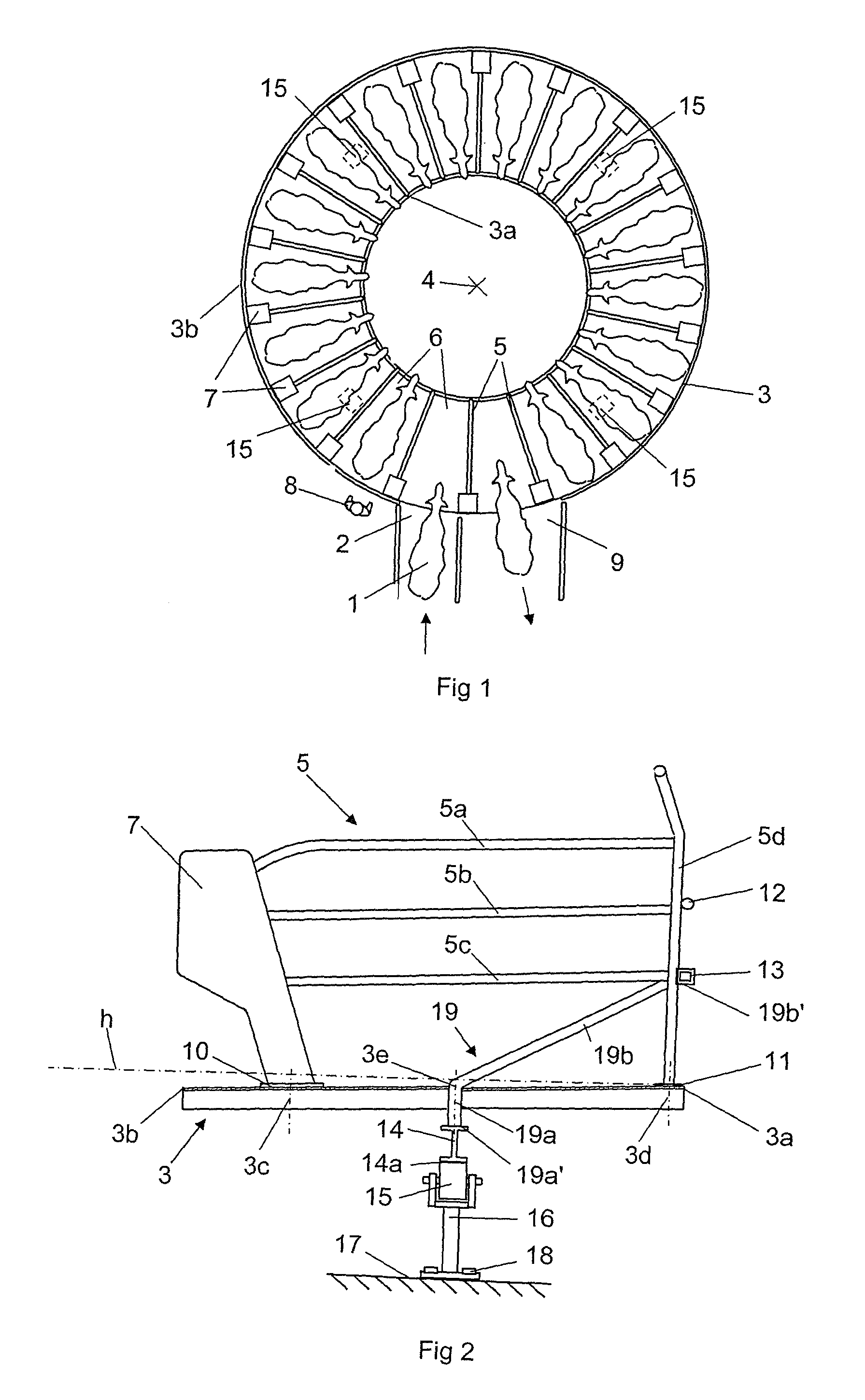
[0016]FIG. 1 shows a rotary parlour for milking of cows 1. The cows 1 to be milked are arranged to walk through an entry 2 to enter an annular platform 3. The platform 3 is rotatably arranged around a substantially vertical axis 4. A plurality of fence arrangements 5 are mounted on the platform, which divide the platform 3 into stalls 6 for receiving individual cows 1. In this case, the fence arrangements 5 have a substantially radial extension on the platform 3 in relation to the vertical axis 4. The fence arrangement 5 comprises a stiff cabinet 7 arranged at an outer radial position of the platform 3, which constitute a supporting element of the fence arrangement 5. The cabinet 7 has an inner space, which may accommodate milking equipment and other components in the stall 6. In this case, the stalls 6 are arranged such that the cows face inwards from the stalls 6 and operators 8 work from the outside of the annular platform 3. An operator 8 may, for example, attach milking members...


PUM


Abstract

The invention relates to a rotary parlour for milking of animals. The rotary parlour includes an annular platform (3) having a surface to support animals (1) to be milked, a circular rail member (14) arranged on an underside of the platform (3) connected to the platform (3) in at least one position (3e), a plurality of rolling members (15) adapted to be in contact with the rail member (14) such that the platform (3) is rotatably arranged on the rolling members (15) and at least one stiff object (7, 13) arranged on the upper side of the platform (3) and connected to the platform (3) in a at least one position (3c, 3d). Further more, the rotary parlour includes a rigid connection between the object (7, 13) and the rail member (14) which includes a bar arrangement (19).

Description

THE BACKGROUND OF THE INVENTION AND PRIOR ART[0001]The present invention relates to a rotary parlour for milking of animals, wherein the rotary parlour comprises an annular platform having a surface to support animals to be milked, a circular rail member arranged on an underside of the platform connected to the platform in at least one position, a plurality of rolling members adapted to be in contact with the rail member such that the platform is rotatably arranged on the rolling members and at least one stiff object arranged on the upper side of the platform and connected to the platform in a at least one position.[0002]The size of a rotary parlour must be adapted to individual farmer's available space and number of cows. A platform of a rotary parlour adapted to receive about 20 to 40 cows is too large to be transported. Therefore, the assembly of rotary parlours in situ is required. Milking cows have a weight of about 600-900 kg. The platform of a rotary parlour has to have a str...

Claims


Application Information

Patent Timeline
Patent Type & Authority Patents(United States)
IPC IPC(8): A01K1/12
CPCA01K1/126
Inventor CHAPMAN, JOHN
Owner DELAVAL HLDG AB
Why Eureka
Try Eureka