Vehicle lighting device

a technology for lighting devices and vehicles, applied in semiconductor devices, light sources, lighting and heating apparatus, etc., can solve the problems of difficult to improve heat radiation performance, fear of degradation of luminance characteristics of lamps, etc., and achieve the effect of improving snow melting performan

Inactive Publication Date: 2011-07-26
KOITO MFG CO LTD
View PDF15 Cites 23 Cited by
  • Summary
  • Abstract
  • Description
  • Claims
  • Application Information

AI Technical Summary

Benefits of technology

[0014]One or more embodiments of the invention provide a vehicle lighting device capable of improving a snow melting performance due to an internal convection thereof and a heat radiation performance thereof.

Problems solved by technology

Thus, it is difficult to improve heat radiation performance.
Thus, there is a fear of degradation in the luminance characteristics of the lamp.

Method used


Image

  • Vehicle lighting device
  • Vehicle lighting device
  • Vehicle lighting device

Examples


first embodiment

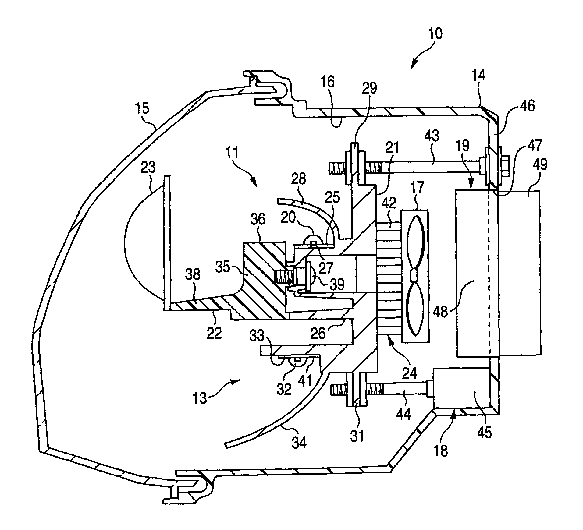
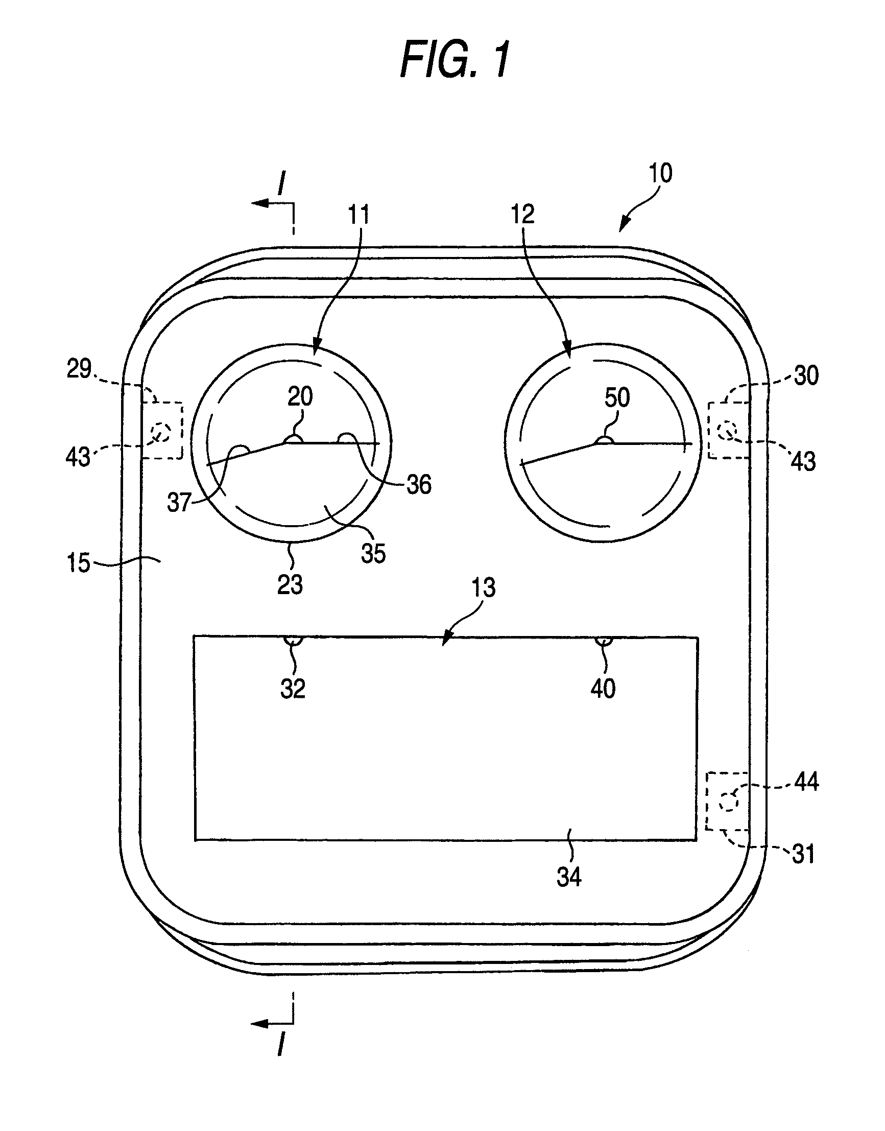
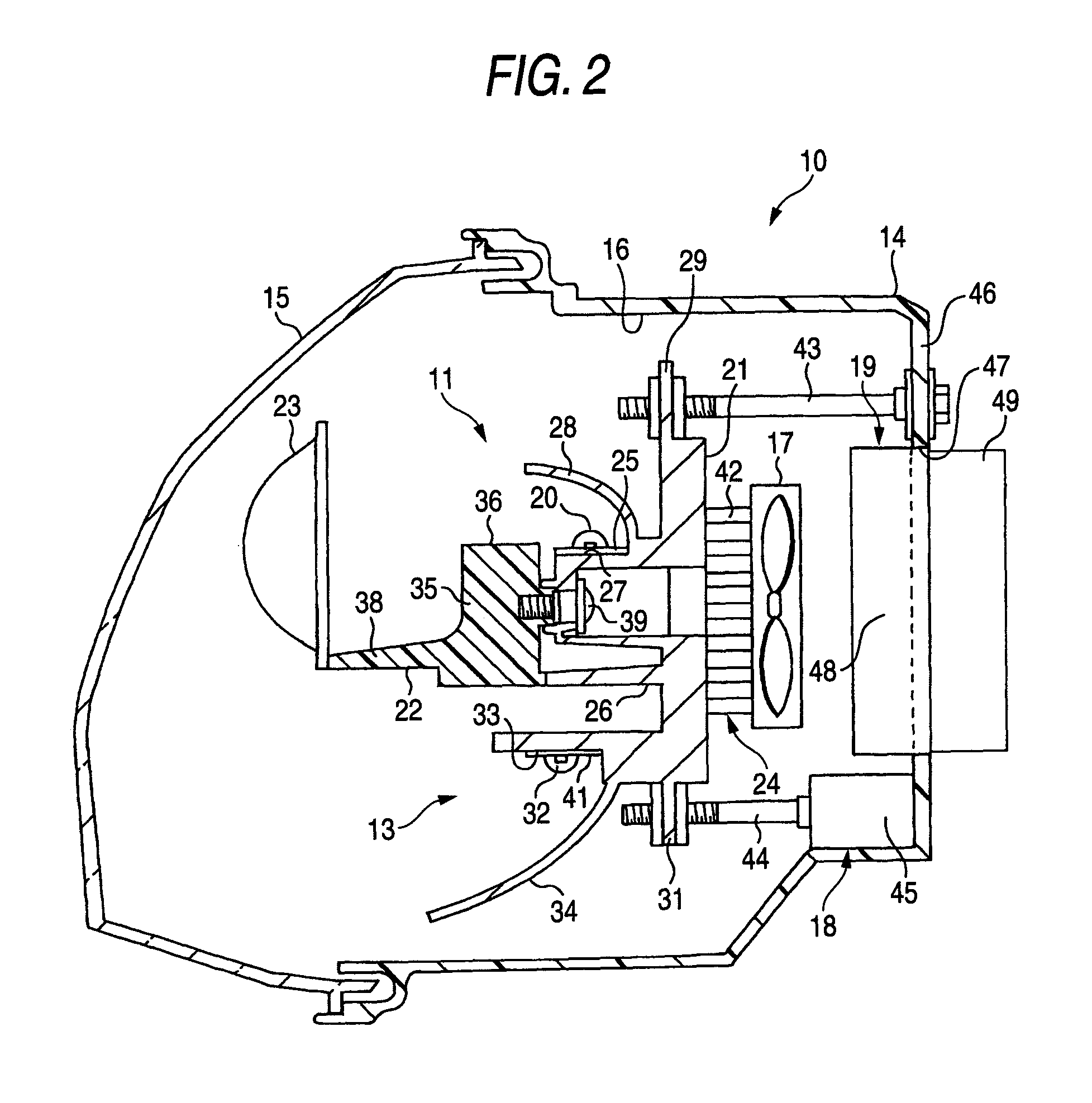
[0033]FIGS. 1 and 2 illustrate a first embodiment of a vehicle lighting device according to the invention. FIG. 1 is a front view illustrating the vehicle lighting device according to the first embodiment of the invention. FIG. 2 is a cross-sectional view taken on line I-I shown in FIG. 1, which illustrates the vehicle lighting device illustrated in FIG. 1. Incidentally, in the following description, the terms “front”, “rear”, “left” and “right” are used according to directions from a vehicle. For example, a left side viewed in FIG. 2 is the front side of a vehicle.

[0034]A vehicle lighting device 10 according to the present embodiment is attached to a front end of a vehicle. A first light source unit 11 and a second light source unit 12, which are of the poly-ellipsoid (PES) type for low beam type headlamps, are placed on an upper half of the vehicle lighting device 10. A third light source unit 13 of the reflector type for high beam type headlamps is placed on a lower half of the v...

second embodiment

[0061]Next, a second embodiment of a vehicle lighting device according to the invention is described below with reference to FIG. 3. FIG. 3 is a cross-sectional view illustrating the vehicle lighting device according to the second embodiment of the invention, which corresponds to a cross-sectional view taken on line I-I shown in FIG. 1. Incidentally, in the following description of the second embodiment, the description of each component, which overlaps with that of the same component or a component having a similar function in the aforementioned first embodiment, is simplified or omitted.

[0062]As illustrated in FIG. 3, the vehicle lighting device 60 according to the present embodiment is configured so that the bracket-side heat transfer member 24 has a plurality of longitudinal fins 51 laterally arranged at intervals on the rear surface side of the bracket 21, that the body-side heat transfer member 61 is extended to a top plate 63 with longitudinal fins 62 being along the rear pla...


PUM


Abstract

A vehicle lighting device is provided with: a lamp chamber defined by a lamp body and a cover; a light source unit including a semiconductor light emitting element as a light source and provided within the lamp chamber; a metallic heat transfer member attached to the lamp body and penetrating between an outside and an inside of the lamp chamber; and an air blower disposed between the light source unit and the heat transfer member so that an air blowing direction of the air blower directs toward the heat transfer member.

Description

[0001]This application claims foreign priority from Japanese Patent Application No. 2007-244284 filed on Sep. 20, 2007, the entire contents of which are hereby incorporated by reference.BACKGROUND OF THE INVENTION[0002]1. Field of the Invention[0003]The present invention relates to a vehicle lighting device a headlamp or the like using a semiconductor light emitting element (hereinafter referred to as an LED) as a light source and having a heat radiation structure.[0004]2. Background Art[0005]As an example of a conventional vehicle lighting device Patent Document 1 discloses a vehicle lighting device provided with a ventilating path formed inside an outer housing and an air blowing fan in the ventilating path.[0006]As illustrated in FIG. 4, the vehicle lighting device 70 disclosed in the Patent Document 1 is configured to attach each outer lens heating portion 72 to each LED 71 serving as a light source so that heat is transferred to each outer lens heating portion 72 from an associ...

Claims


Application Information

Patent Timeline
Patent Type & Authority Patents(United States)
IPC IPC(8): B60Q1/00
CPCF21S48/1159F21S48/325F21V29/02F21W2101/10F21Y2101/02F21V29/74F21V29/83F21Y2115/10F21S41/148F21S45/435F21S45/60F21W2102/00
Inventor YASUDA, YUJI
Owner KOITO MFG CO LTD
Why Eureka
Try Eureka