Device having a point and a spatial sound generating-means for providing stereo sound sensation over a large area

a technology of spatial sound and stereo sound, applied in the direction of stereo sound arrangment, transducer details, electrical transducers, etc., can solve the problem that the stereo playback of external loudspeakers such as ‘ghettoblasters’ is not perceived as true stereo playback, and the footprint and wiring issues are associated with the device. achieve the effect of giving a relatively large area

Inactive Publication Date: 2011-07-26
MMD HONG KONG HLDG LTD
View PDF8 Cites 2 Cited by
  • Summary
  • Abstract
  • Description
  • Claims
  • Application Information

AI Technical Summary

Benefits of technology

[0005]It is an object of the invention to provide a compact sound reproduction device capable of giving a stereo sound sensation over a relatively large area.
[0017]Due to excitation of the object on which the first part is placed, a much richer and better audible sound is obtained.

Problems solved by technology

This usually results in devices with external loudspeakers separated from each other by a considerable distance and the associated footprint and wiring issues.
However, this requires a space with enough distance between the loudspeakers, which is not always available and often also requires wiring.
However, although such compact devices have been developed and sold, the stereo playback of these devices such as ‘ghettoblasters’ is not perceived as true stereo playback because the loudspeakers are spaced very close to each other.
However, such techniques may typically reduce the “sweet spot” (i.e. the area in which a good or acceptable stereo sound is produced), which sometimes becomes impractically small since consumers typically do not sit exactly in front of such a sound device.
Furthermore, such techniques are usually complicated.
Typically, compact devices for producing stereo sound have the drawback that, although they do provide stereo sound only in or near the sweet spot, the positions in which this is achieved is limited to usually a rather small area right in front of the device.

Method used


Image

  • Device having a point and a spatial sound generating-means for providing stereo sound sensation over a large area
  • Device having a point and a spatial sound generating-means for providing stereo sound sensation over a large area
  • Device having a point and a spatial sound generating-means for providing stereo sound sensation over a large area

Examples


Embodiment Construction

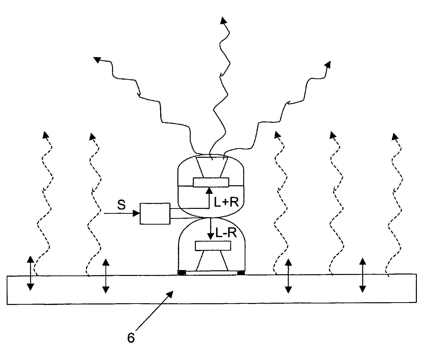
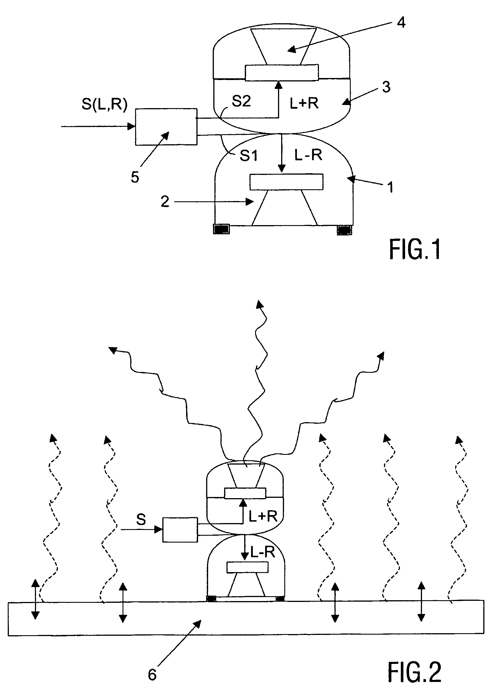
[0035]FIG. 1 schematically shows a compact stereo device according to the invention.

[0036]The stereo device has an input for an incoming stereo signal S comprising a left (L) and a right (R) signal, and an interconnected first (1) and second part (3) comprising a first (2) and a second (4) sound-generating means, respectively. The first part 1 is formed so as to couple soundwaves generated by the first sound-generating means into a surface when placed upon this surface. Basically, in this example, soundwaves are effectively coupled with the housing and via the housing with, for instance, a table top or directly into the table top. Normally, sound-generating means are positioned inside loudspeakers so that they are decoupled with the housing and the outside world as much as possible. In the first part, the opposite effect is sought, a large coupling is present to the outer envelope, to an elongated element or to a surface upon which the first part is placed. The device has means 5 fo...


PUM


Abstract

A device is described, having a first (2) and a second (4) sound-generating means and an input for a stereo signal (S) comprising left (L) and right (R) sound signals. The device has an interconnected first (1) and second (3) part comprising a first (2) and a second (4) sound-generating means, respectively. The first part (1) is formed so as to couple soundwaves generated by the first sound-generating means (2) into a surface (6) when placed upon said surface (6), and the device has means (5) for sending a first signal (S1), which is a composite of the left (L) and right (R) sound signals, to the first sound-generating means (2) of the first part (1), and a second signal (S2), which is a different composite of the left (L) and right (R) sound signals, to the second sound generating means (4) of the second part (3).

Description

FIELD OF THE INVENTION[0001]The invention relates to a device having a first and a second sound-generating means and an input for a stereo signal comprising left and right sound signals.BACKGROUND OF THE INVENTION[0002]Devices comprising two sound-generating means are known and widely used.[0003]Spatial localization of sound has always been considered to be of paramount importance in audio reproduction devices. Contemporary sound reproduction devices are required to have at least stereo playback capabilities, and two or more loudspeakers are conventionally provided for such facilities. This usually results in devices with external loudspeakers separated from each other by a considerable distance and the associated footprint and wiring issues. However, this requires a space with enough distance between the loudspeakers, which is not always available and often also requires wiring. In many circumstances, more compact devices would be preferred. However, although such compact devices h...

Claims


Application Information

Patent Timeline
Patent Type & Authority Patents(United States)
IPC IPC(8): H04R5/02H04R5/00H04R1/40H04S1/00
CPCH04R1/403H04S1/002H04R1/40H04S1/00H04R2420/01
Inventor SCHOBBEN, DANIEL WILLEM ELISABETHVAN DELDEN, MARTINUS HERMANUS WILHELMUS MARIA
Owner MMD HONG KONG HLDG LTD
Why Eureka
Try Eureka