Protective tape joining apparatus

a technology of joining apparatus and protective tape, which is applied in the direction of electrical equipment, chemistry equipment and processes, lamination ancillary operations, etc., can solve the problems of preparing various frame members with different releasing properties, and not being able to remove them with ease, so as to achieve the effect of easy adjustment of the height of the chuck tabl

Inactive Publication Date: 2011-08-02
NITTO DENKO CORP
View PDF5 Cites 3 Cited by
  • Summary
  • Abstract
  • Description
  • Claims
  • Application Information

AI Technical Summary

Benefits of technology

[0008]An object of this invention is to cut a protective tape along an outer periphery of a semiconductor wafer with good finished quality while applying appropriate tension to an unnecessary portion of the protective tape protruding from the semiconductor wafer and to separate the unnecessary protective tape from a chuck table with ease.
[0020]According to the protective tape joining apparatus of the present invention, in order to join the supplied protective tape to the semiconductor wafer and a wafer support part, the joining roller rolls on the protective tape along the plurality of linear tape support parts of the tape support frame. That is, the joining roller rolls on the protective tape smoothly while keeping a certain height, without getting caught in the linear grooves each located between the linear tape support parts.
[0023]Accordingly, the cut protective tape is separated starting from one end of the linear shape, that is, the joining starting position or the joining termination position. Thus, the protective tape can be readily separated and removed from the tape support frame.
[0027]Accordingly, the state that the tension is applied to the protective tape on the cutter blade traveling groove becomes more reliable and uniform in the circumferential direction. Thus, the protective tape can be cut along the cutter blade traveling groove with good accuracy.
[0038]Accordingly, it is possible to prevent the tape support frame from being subjected to heat and to avoid such a disadvantage that the protective tape cannot be separated and removed with ease from the tape support frame due to the increased joining strength thereof.
[0041]With this configuration, the shim plate can be inserted / removed without removal of the bolt. That is, the height of the chuck table can be changed with ease in the state that the coupling part and the attachment seat part are coupled by the bolt.

Problems solved by technology

That is, in a case where an unnecessary tape after cut out is separated from the protective tape, the unnecessary tape disadvantageously comes into close contact with the frame member because of a flat surface of the frame member, and, consequently, cannot be removed from the frame member with ease.
However, there are various protective tapes which are different in adhesive force from one another.
Consequently, there arises such a disadvantage that various frame members with different releasing properties must be prepared previously depending on the types of the protective tapes.

Method used


Image

  • Protective tape joining apparatus
  • Protective tape joining apparatus
  • Protective tape joining apparatus

Examples


Embodiment Construction

[0055]With reference to the drawings, hereinafter, description will be given of preferred embodiments of this invention.

[0056]FIG. 1 is a perspective view showing a general configuration of a protective tape joining apparatus.

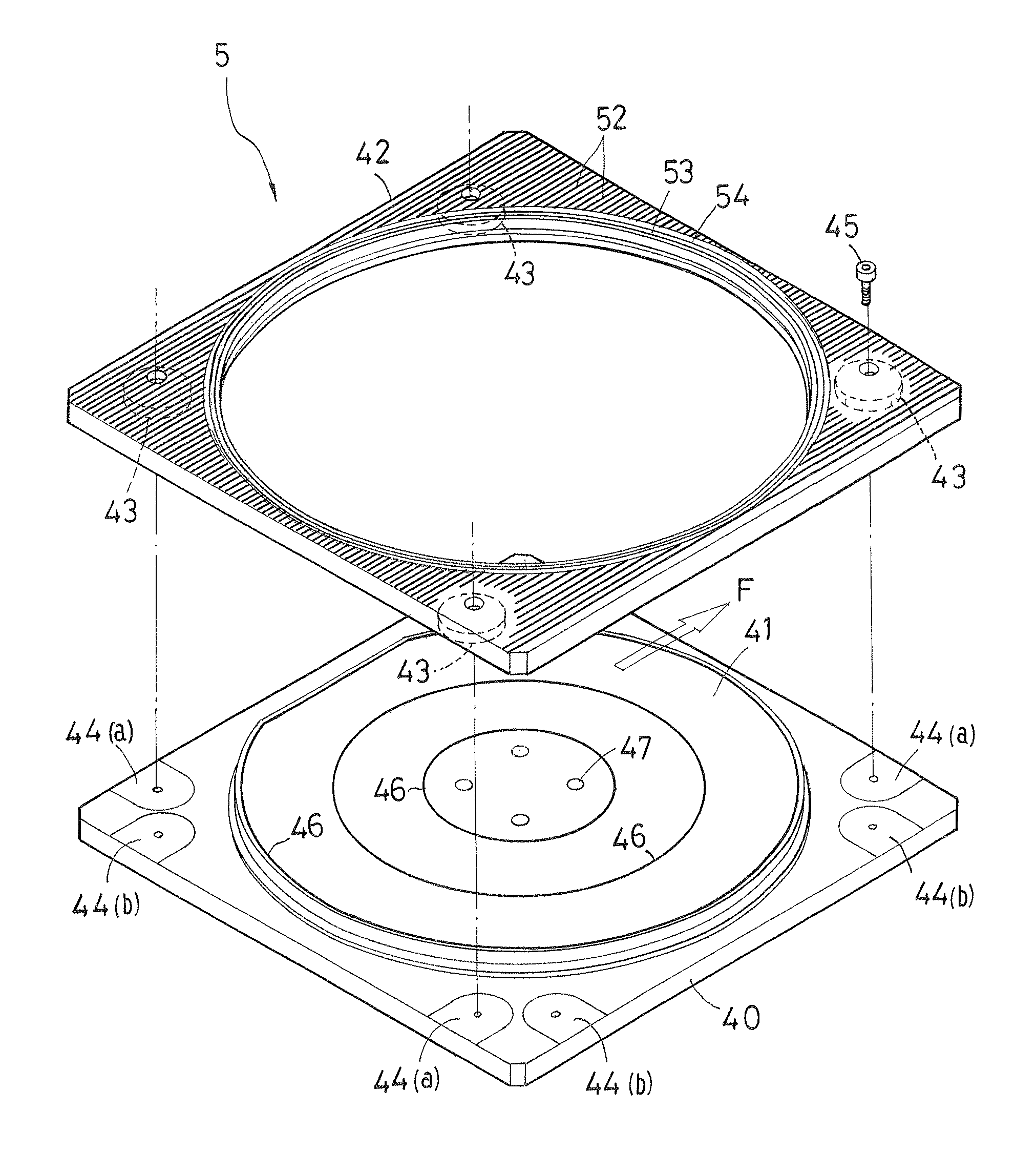
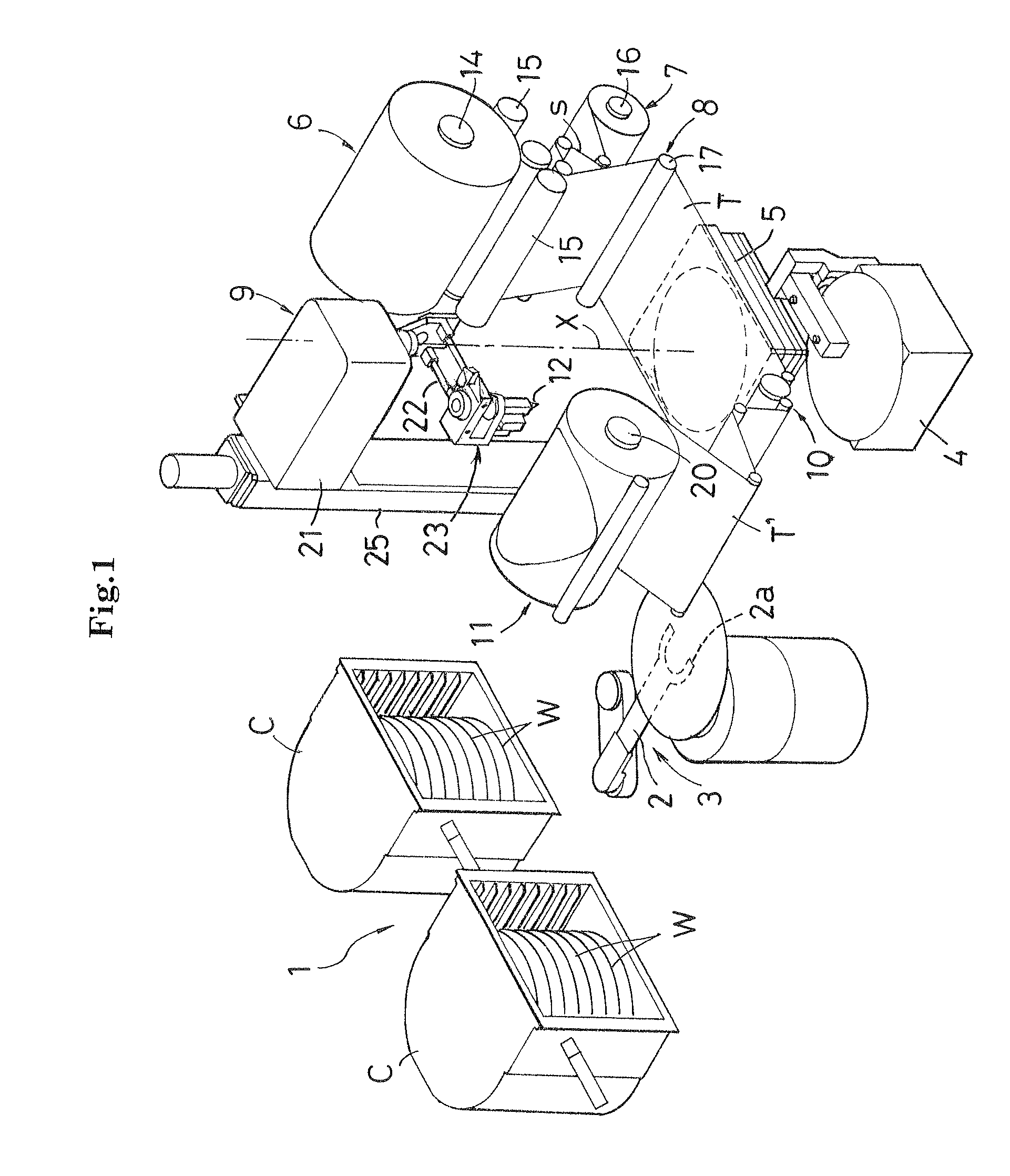
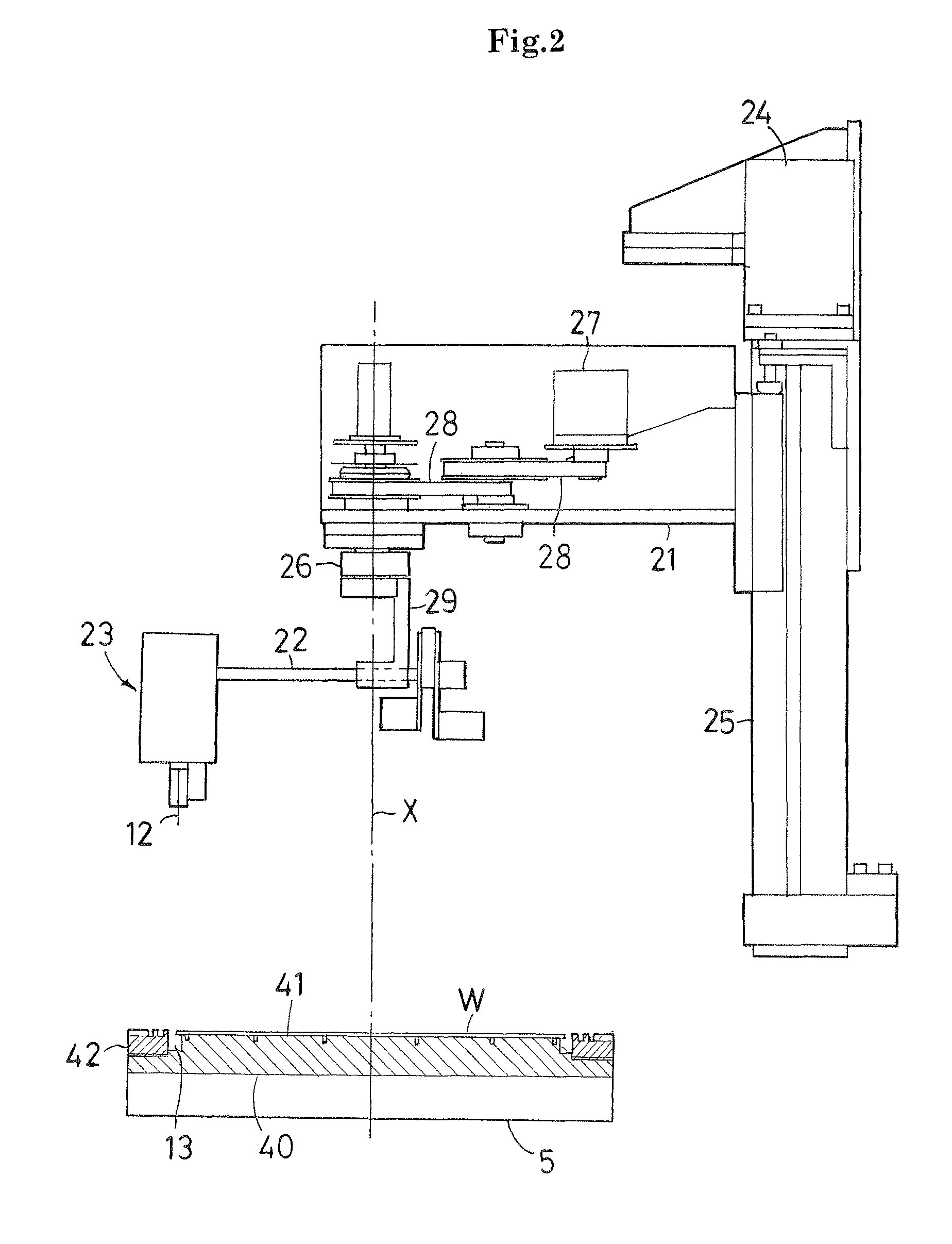
[0057]This protective tape joining apparatus includes: a wafer supply / collection part 1 with a cassette C mounted therein for housing a semiconductor wafer (hereinafter, simply referred to as a “wafer”) W; a wafer transport mechanism 3 that has a robot arm 2; an alignment stage 4; a chuck table 5 that suction-holds the wafer W placed thereon; a tape supply part 6 that supplies a protective tape T provided with a separator s onto a position above the wafer W; a separator collection part 7 that separates the separator from the protective tape T supplied from the tape supply part 6 and collects the separator s; a joining unit 8 that joins the protective tape T to the wafer W placed on and suction-held by the chuck table 5; a tape cutting device 9 that cuts out the...


PUM

PropertyMeasurementUnit
heightaaaaaaaaaa
heat insulatingaaaaaaaaaa
adhesive forceaaaaaaaaaa

Abstract

A chuck table is configured with a table main body having a wafer placement part holding a wafer placed thereon, and an annular tape support frame provided outside the wafer placement part with a cutter blade traveling groove being interposed therebetween. The tape support frame has, at a top face thereof, a plurality of linear grooves arranged in parallel in a tape joining direction, a large number of linear tape support parts each located between the linear grooves, and an annular tape support part supporting the protective tape at an outer side of the cutter blade traveling groove.

Description

BACKGROUND OF THE INVENTION[0001](1) Field of the Invention[0002]This invention relates to a protective tape joining apparatus that joins a protective tape to a surface of a semiconductor wafer subjected to surface treatment and cuts the protective tape along an outer periphery of the semiconductor wafer.[0003](2) Description of the Related Art[0004]In order to join a protective tape to a surface of a semiconductor wafer (hereinafter, appropriately referred to as a “wafer”) and then cut the protective tape, there has been known a device having the following configuration. For example, such a device is configured with a chuck table and an annular frame member that surrounds the chuck table. Specifically, the wafer is placed on and held by the chuck table and the protective tape is supplied onto the surface of the wafer. Next, a joining roller rolls on a surface of the protective tape to join the protective tape to the surface of the wafer and the frame member. Next, a cutter blade tr...

Claims


Application Information

Patent Timeline
Patent Type & Authority Patents(United States)
IPC IPC(8): B32B43/00
CPCH01L21/67132H01L21/67092Y10T156/12Y10T156/1343H01L21/78
Inventor YAMAMOTO, MASAYUKIKANESHIMA, YASUJI
Owner NITTO DENKO CORP
Why Eureka
Try Eureka