
Multistage crop roller

a crop roller and multi-stage technology, applied in the field of multi-stage crop rollers, can solve the problems of crop residues that interfere with the cash crop planting process, crop residues that prevent adequate seed-soil contact, and require frequent stops, so as to achieve the effect of suppressing vibration transmission

Active Publication Date: 2011-08-02
US SEC AGRI
View PDF26 Cites 15 Cited by
  • Summary
  • Abstract
  • Description
  • Claims
  • Application Information

AI Technical Summary

Benefits of technology

The invention is a system for stopping crop growth at different stages. It consists of a main frame, two roller frames, and a compression frame. The first roller is a smooth drum and the second roller is a central cylindrical drum with crimping bars. The system is designed to flatten and crimp crops, and it also suppresses vibrations and maintains contact with the ground as it moves over uneven terrain. The technical effect of this invention is to provide a reliable and effective tool for stopping crop growth at different stages.

Problems solved by technology

Although herbicide application effectively kills the cover crops, there may be problems associated with unintended over-spray, spray drift, and undesirable chemical run-off.
The stalks and associated crop residue subsequently interfere with the cash crop planting process, particularly for cover crops (such as rye) that generate a large amount of biomass.
As a result, frequent stops are required to clean accumulated cover crop residue from planting units.
In addition, cover crop biomass often causes hair-pinning, a condition in which crop residue prevents adequate seed-soil contact.
However, operators of the crimping devices frequently complain of the excessive vibrations associated with the devices.
The excessive vibrations commonly result in an increased heart rate, headache, stomach pain, and lower back pain.
Prolonged exposure to these types of excessive vibrations may lead to spinal degeneration.
Although the severity of the vibrations can be reduced by simply reducing operating speed, this is generally regarded as an economically impractical solution, particularly in view of the relatively higher operating speeds achievable using herbicide-oriented methods.
Smaller farming operations (especially vegetable farms) cannot use the large-scale rollers because their tractors are generally smaller and lack the power and capability required to operate the larger and heavier rollers.

Method used


Image

  • Multistage crop roller
  • Multistage crop roller
  • Multistage crop roller

Examples


Embodiment Construction

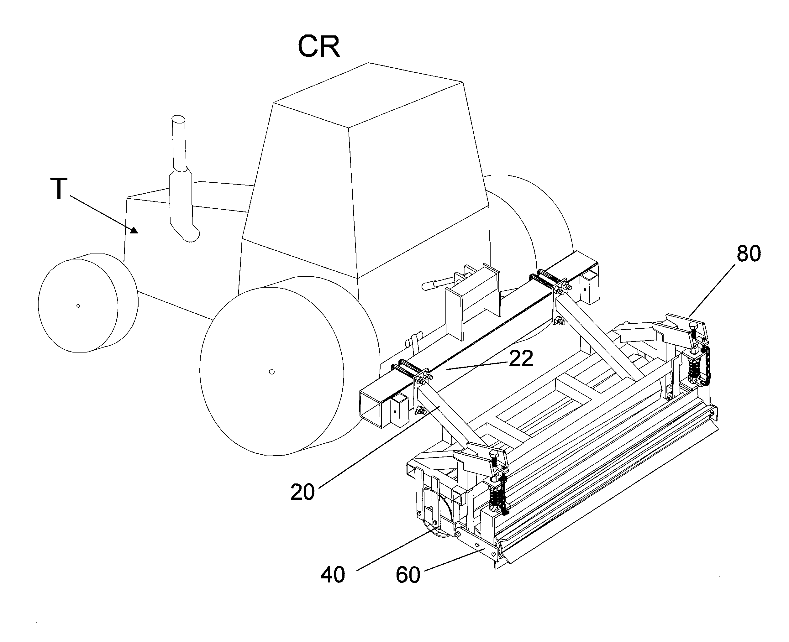
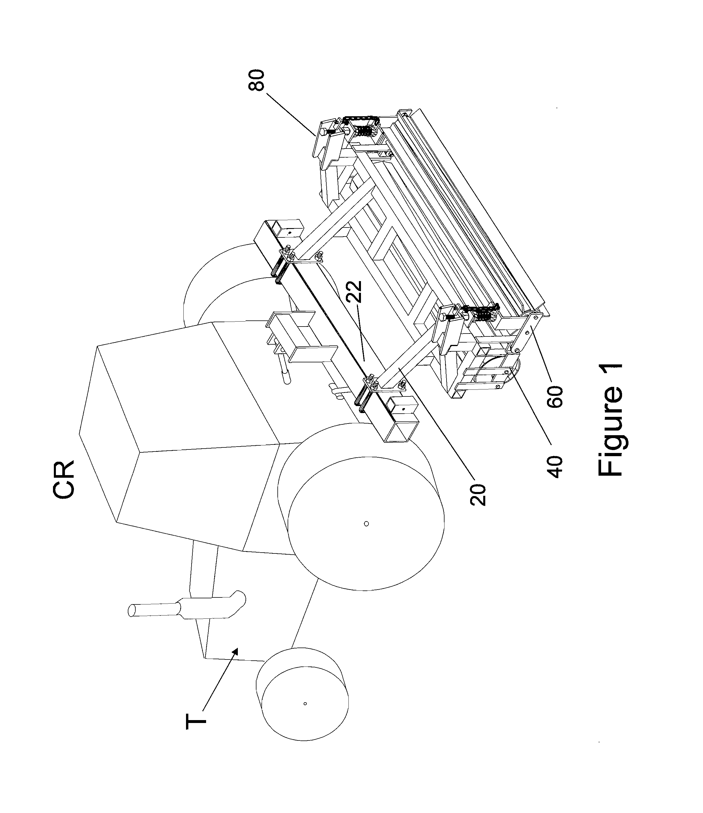
[0014]The multistage crop roller CR of current invention is generally shown in FIG. 1. In the preferred embodiment, the crop roller CR comprises a two roller-stage system that is towed across a field by a tractor T. In alternative embodiments, the crop roller CR may be self-propelled or may be propelled by any means known in the art and may include multiple additional roller stages.

[0015]As generally shown in FIG. 1, the multistage crop roller CR comprises a main frame 20, a first roller frame assembly 40, a second roller frame assembly 60, and a compression roller frame assembly 80. In the preferred embodiment, the crop roller CR is connected to the tractor T via the tool bar 22.

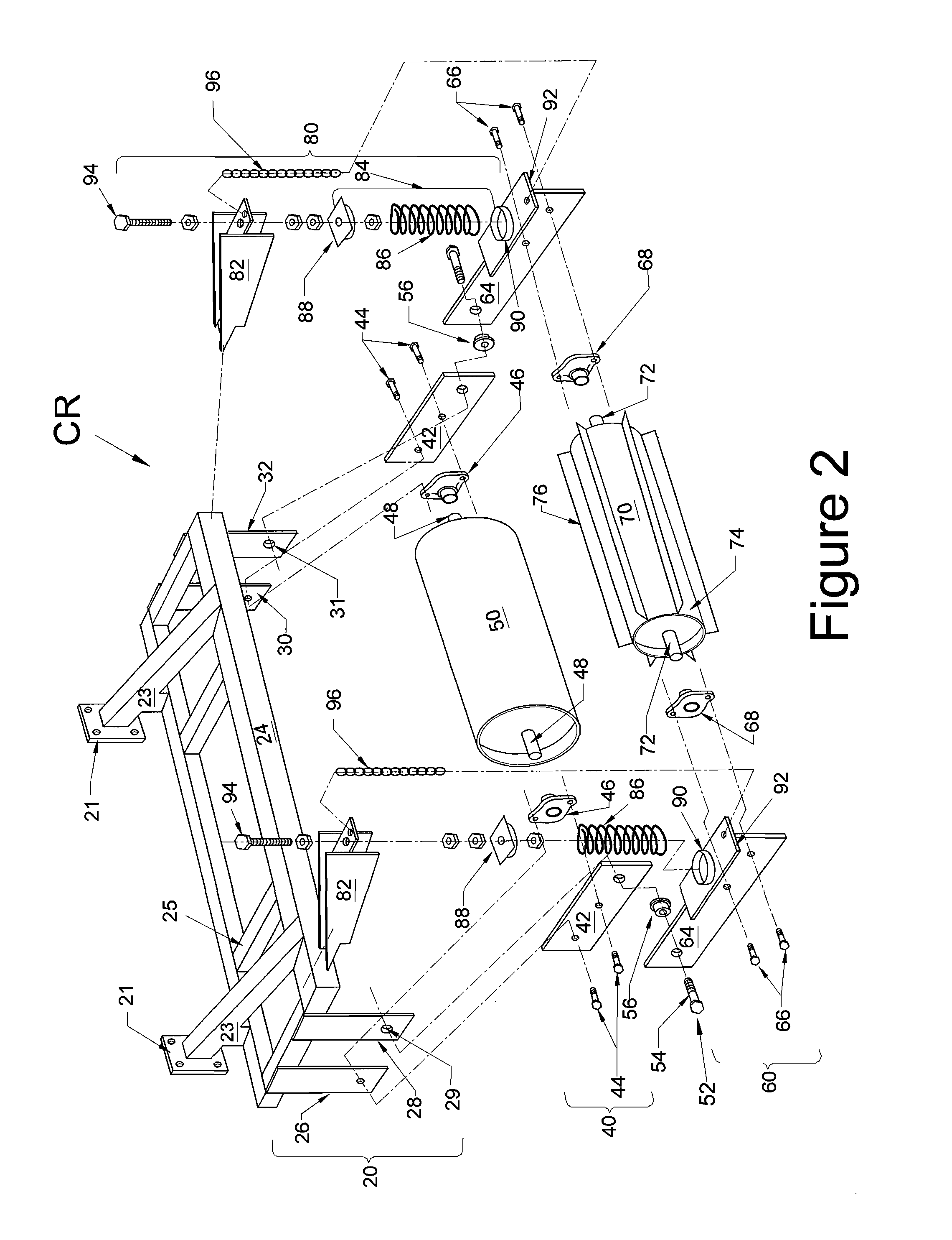
[0016]FIG. 2 shows the preferred embodiment of the multistage crop roller CR. The crop roller CR main frame 20 comprises a rectangular structural frame 24 with horizontally extending supporting members 25. Angular supports 23 extend upwardly from the rectangular frame 24 and terminate in a flange plate 21. ...


PUM


Abstract

The multi-stage crop termination system includes a main frame assembly connected to first and second roller frames. A first roller is installed in the first roller frame and a second roller is installed in the second roller frame. A compression frame extends between the main frame and the second roller frame so that a downwardly compression force is applied to the second roller. In the preferred embodiment, the first roller is a smooth drum and the second roller is a central cylindrical drum with a plurality of crimping bars extending outwardly from the drum. In operation, crops are flattened by the first roller and then crimped by the second roller. A pivot joint between the first roller frame and the second roller frame ensures that the second roller is able to maintain contact with the ground as the system traverses uneven terrain.

Description

[0001]The present invention relates to a system and method for mechanically terminating cover crops. Specifically, the current invention relates to a multi-stage roller assembly designed to roll over and crimp crops.BACKGROUND OF THE INVENTION[0002]Cover crops are an important part of most no-till conservation systems, but they must to be managed correctly to fully realize their potential benefits. Among other things, these benefits include a reduction in soil erosion and the suppression of weed pressure. For example, in southern portions of the US, rye (Secale Cereale. L.) is commonly used as a winter cover crop. Rye improves soil properties and releases chemicals that suppress weeds. Rye also reduces soil compaction, facilitates water and air infiltration, and increases soil organic matter content.[0003]At the end of a selected cover crop growing cycle, the cover crops are terminated so that a cash crop can emerge and thrive. Termination of the cover crop allows the cash crops to ...

Claims


Application Information

Patent Timeline
Patent Type & Authority Patents(United States)
IPC IPC(8): A01B21/02
CPCA01B29/02A01B49/027
Inventor KORNECKI, TED S.
Owner US SEC AGRI
Learn More